¾ speed needle-drop recording is the branchild of Robert Kellner, a customer of Stereo Lab.
Bothered by excessive distortion on inner grooves of LPs, Robert was enthusiastic about half-speed needle drops. But he discovered that, whilst the improvement in distortion performance was evident, there were significant mechanical compromises in working at half-speed.
Changing resonances
Slowing the record speed to half its design value upsets two resonant systems:
The inertia of the arm bouncing on the cartridge vertical compliance (the arm resonance); and
The moment of inertia of the rotating turntable "bouncing" (varying its angular momentum) on the compliance of its drive system. This is the origin of wow and flutter.
Note that the second resonant system is palpable in the case of a belt-drive turntable, but, even a direct drive system has "compliance" in the form of the damping of the servo system.
Whilst it's true that the disturbing signals due to record imperfections are halved too when the record rotates at half speed, transients will still excite the resonant systems at their natural frequency and these natural frequencies are doubled when a half-speed recording is returned to its correct speed in subsequent digital processing.
Mechanical design could, of course, rectify this: the inertia of the arm could be increased and much more massive counterweight provided, or the cartridge could have dramatically increased compliance.
Similarly, the rotating platter and drive system could be optimised for rotation at half normal speed. But these are significant engineering tasks which go well beyond the relatively simple task of arranging the motor to turn more slowly.
Half of a half
Robert's idea was to ask if it would be possible to scan the record more slowly than normal, but not as slowly as half speed, his suggestion being 25% slow at 25RPM.
In this way, once speeded up in software, the cartridge/arm resonance and the drive/ platter resonance would only change by 33% (remember, the reciprocal of 3⁄4 = 4⁄3) which is a change small enough to keep the performance within acceptable limits.
In his quest for reduced speed capability turntables, Robert reached out to JP Jones of Fidelis Analog (http://fidelisanalog.com) who specialise in upgrading high-end Technics' tuntables to check whether their MN6042 upgrade for the Technics SP-10 Mk 3 could be able to achieve 25RPM.
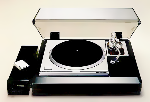
Technics SP-10
The SP-10 was the world's first turntable to use a direct-drive system. The turntable platter weighs 2.8 kg and every platter produced was meticulously adjusted for optimal dynamic balance.
The turntable's rotational speed was electronically controlled with a choice of speeds of 33⅓ and 45 RPM. The SP-10 was used by broadcasters, including the BBC, and remains a highly sought after "reference deck".
A practical solution
JP Jones of Fidelis Analog confirmed in experiments exactly that which Robert had anticipated, that half-speed was indeed too far outide the optimum range of the servo control system, but that 25 RPM remained solidly within range and excellent speed stability could be guaranteed.
At this point, you can be forgiven for thinking, will this relatively small speed change be worth all the trouble?
The answer is a definite, yes. But to explain that we need to look more closely at the work of Professor Hunt of Harvard University and his co-workers (see panel and below).
The work of professor Hunt and his PhD students
Frederick Hunt was a young professor of physics at Harvard in 1936 when he was given the task of making phonograph recordings of the university's tri-centenary festival.
In order to improve the quality of the recordings, Hunt and a series of talented collegues and doctural students, made enormous headway in the understanding of the interaction of the stylus and groove.1,2,3
Tracing distortion
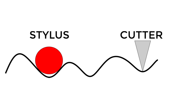
The origin of all tracing distortion is that a groove cut by a flat-faced chisel is being read by a rounded (conical or elliptical) stylus. Tracing distortion is responsible for the majority of distortion (and not just harmonic distortion) when reproducing gramophone records.
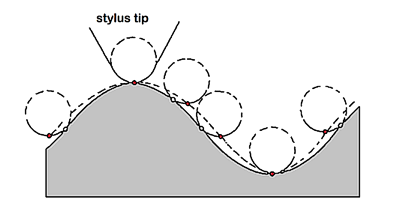
The figure above shows the cross section of a vertically modulated groove (the grey is the disc in cross-section).
The figure clearly illustrates that the motion of the playback stylus fails to follow the groove's shape. The problem being that the point of contact between the spherical playback stylus and the groove wall wanders as it traces the groove, causing the stylus to trace a path indicated by the dashed line.
The team at Harvard, in a feat of heavy-duty analytical geometry analysed1,2 the path of the stylus - and thereby the reproduced signal.
They demonstrated that tracing distortion was not only present in vertical modulated discs, but also in discs with lateral modulation — with one vital difference.
The two groove walls in the case of lateral modulation act like a push-pull amplifier so that the DC (0Hz) term and the even harmonic distortion terms cancel out.7
It is to Hunt that we owe the fact that (mono) records are laterally modulated. Until Hunt's work, discs were recorded both laterally and vertically and each system had its adherents. The two papers by Hunt and his associates 1,2 put that argument to bed for ever. In fact tracing distortion in lateral recording was so improved (compared with vertical modulation) that people forgot about it for many years.
Stereo and the need for speed
❝.... distortion is .. proportional to the stylus radius, the recording velocity and inversely proportional to the square of the groove velocity. ❞
As described in the panel, the distortions which arise in following a groove with a stylus point of finite size were first analysed in detail by Pierce and Hunt¹ and later by Lewis and Hunt². Within a few years, their work was comprehensively embraced by industry.5
As explained, they discovered that tracing distortion due to lateral modulation only (as in a mono LP) could be easily controlled provided the various relationships between the groove size, record speed and stylus dimensions were observed.
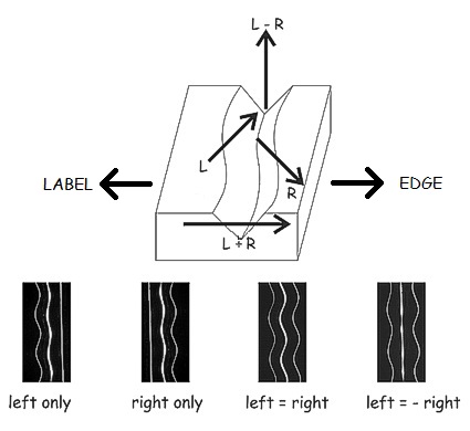
But the coming of the stereo LP brought bad news. Both theoretical and empirical studies indicated that each wall of the groove of the 45°- 45° stereo system (illustrated right) is equivalent to a channel with vertical recording.
In this single-sided system there will be both second- and third-harmonic distortion, the second harmonic component being the dominant distortion term and about 10 times worse than with lateral recording. The distortion is approximately directly proportional to the stylus radius, the recording velocity and inversely proportional to the square of the groove velocity.6
Distortion can be controlled by reducing the dimension of the scanning stylus (an option which wasn't seized upon until many years later). And it may also be controlled by keeping the modulation velocity low. But recording and mastering engineers are under great pressure to keep recorded velocity high because customers and radio DJs hate "quiet" records.
That leaves the reciprocal of S² where the squared term in speed is all important. To put it bluntly, distortion performance is predominated by the turning speed of the record. Nothing has as great an effect on distortion as the speed of the record past the stylus. And this is all the more troublesome because the tangential speed of the record groove decreases as it plays.
Downward spiral
The RIAA standard limits of inside and outside groove diameters of an LP record are:
• Max outside recorded groove diameter: 11.5" or 292.1mm (radius = 146.05mm)
• Minimum inside recorded groove diameter: 4.75" or 120.6mm (radius = 60.3mm)
Given that a record turns at a constant 33⅓ RPM, which equates to 0.556 turns per second, the velocity of the stylus within the groove is:
• 0.510m/s (20 inches per second) on the outermost turn, and
• 0.210m/s (8.3 inches per second) on the innermost.
A speed ratio of 2.4 to 1. Applying our square term, we can say this will results in distortion six times worse at the innermost groove spiral compared with the outermost.
Plugging in the numbers
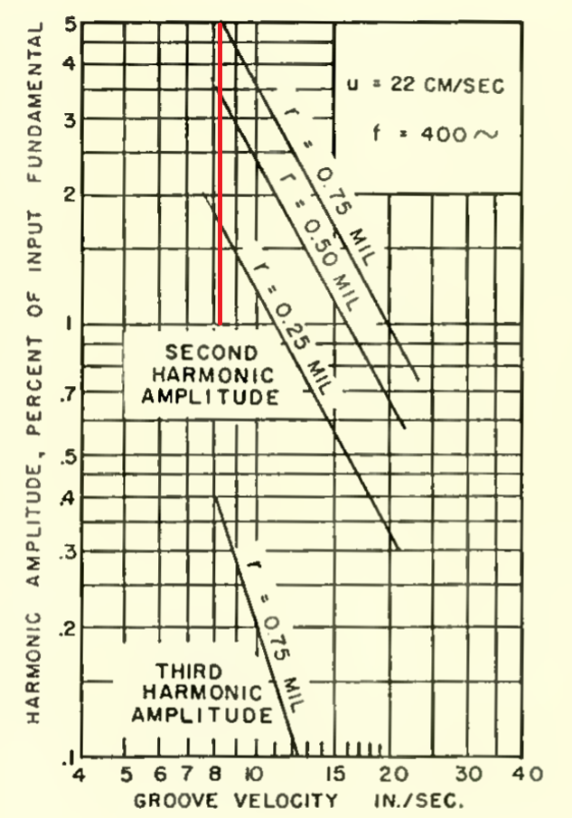
The mighty RCA took the results of Pierce and Hunt¹ and Lewis and Hunt² and compared them to a series of computer simulations at the start of the stereo era, the results of which are shown (left).6
Their results indicate that the distortion levels on commercial LP discs when scanned with a stereo conical stylus of with a 18µm (0.0007") stylus do indeed rise from an innocuous 1% at the outer diameter velocity to nearly the predicted 6% at the innermost groove spiral (for a modulation velocity of 22cm/s at 400Hz).8, 9
Scale speed
As the steepness of each of the curves illustrate, speed is the most powerful factor here. If we scan an LP record at ¾ speed and speed it up in software afterwards, we are effectively raising the speed of a 33⅓ record to a 44.4 RPM record. We are thus raising the minimum groove velocity at the innermost spiral to 11 inches/sec, and reducing distortion to (¾)² = 9⁄16 of its value if the disc is played at 33⅓ RPM.
Conclusion and operation in Stereo Lab
So, ¾ speed scanning secures a very worthwile reduction in distortion (it's nearly halved) with minimum disruption of the mechanical systems of tonearm and drive system.
Combined with the selection of a Shibata type stylus, a overall reduction of distortion in the "last groove" by a factor of five is possible compared with a conical stylus scanning at 33⅓ RPM.
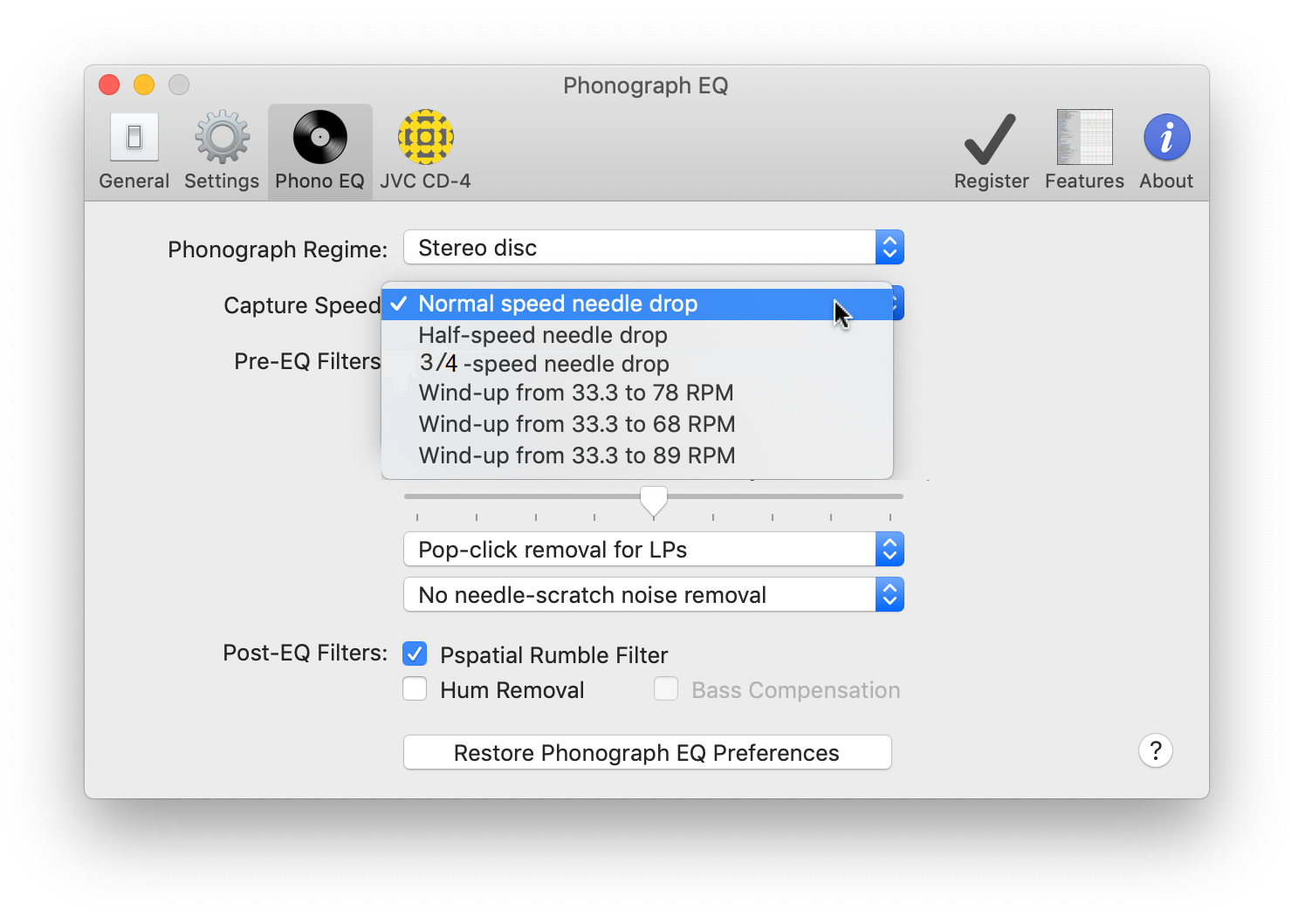
Up-speeding from 25 RPM is accessed in Stereo Lab via the Capture Speed pulldown in the Phono EQ options dialogue.
If your turntable is capable of variable speed, Pspatial Audio have prepared two stroboscope discs to allow the setting of 25 RPM in comparison with mains-lighting frequency.
Printout the pdf file, cut round the perimeter circle and make a 7mm hole in the centre. Place on the turntable like a record. When illuminated with alternating current lighting, the pattern of bars on the stroboscope disc appears stationary when the turntable speed matches 25 RPM. Go to this link for a discussion on the accuracy of mains frequency.
A preliminary demo of ¾ speed scanning and up-speeding in Stereo Lab is given below. The sharp-eared will notice that we didn't quite get the turntable to turn at exactly 25RPM. Nonetheless, the reduction in harmonic distortion is very obvious. The example is taken from an innermost groove recorded at relatively high level so it's a good test of the advanatges of the system. The original 33⅓ needle-drop is first. Afterwards the up-speeded 25 RPM is presented.
Notes and References
1. On Distortion in Sound Reproduction from Phonograph Records. J. A. Pierce and F. V. Hunt
The Journal of the Acoustical Society of America 10, 14 (1938); https://doi.org/10.1121/1.1915951. In this paper, the amplitudes of the harmonic frequencies due to tracing distortion were found by finding the coördinates of the curve traced by the stylus and making a numerical harmonic analysis.
2. A Theory of Tracing Distortion in Sound Reproduction from Phonograph Records. W. D. Lewis and F. V. Hunt
The Journal of the Acoustical Society of America 12, 348 (1941); https://doi.org/10.1121/1.1916111. In this later paper, the harmonic distortion was analysed by expanding an explicit expression for the curve in a power series.
3. The Rational Design of Phonograph Pickups Hunt, F. V. JAES Vol. 10 No. 4, October 1962. This retrospective article sums up Hunt's work and that of his associates.
4. The well known equation for resonance F = [2.Π.√(M.C)] -1 reveals that resonant frequency of mass (M) and compliance (C) changes with the square-root of the mass (or the compliance).
5. Tracing distortion in phonograph records. Corrington, M.S. RCA REVIEW June 1949
6. Tracing distortion in stereophonic disc recording. Corrington M.S. and Murakami, T. RCA REVIEW June 1958
7. In fact two equal and opposite second harmonic terms canel out, but add in the vertical dimension. This is a mathematical description of the well known pinch effect.
8. Later work established that groove deformation due to the passage of the stylus accounts for the slight discrepancy between predicted and measured figures. See: Deformation Distortion in Disc Records. Shiga, T. J. Audio Eng. Soc., vol. 14, p. 208 (July 1966). Mr. Shiga showed that the second harmonic term arising from tracing error is reduced by the effect of deformation error away from resonance.
9. You will sometimes see distortion figures much higher than annotated on Corrington and Murakami's graph. This is because other workers have looked at intermodulation distortion or recorded the distortion results obtained from velocity pickups. With a rising response, the velocity signal has twice as much second-harmonic in relation to the fundamental, and three times as much third-harmonic and so on. Given that we are mostly considering RIAA equalised discs, we believe it's more representative to consider distortion on the displacement signal.

 The SP-10 was the world's first turntable to use a direct-drive system. The turntable platter weighs 2.8 kg and every platter produced was meticulously adjusted for optimal dynamic balance.