The type and quality of the metal used in cables is widely thought to be important in audio applications. Top-end cable prices are eye-watering and represent a significant investment for the vinylista. How much difference is there between a cheap cable and a high-end interconnect?
The conductivity argument
Silver wire is widely considered pre-eminent for analogue audio applications because it is the best conductor of electricity.¹ Silver has a resistivity 7% lower than the next best conductor, copper. But, because silver is so rare and expensive, copper is the preferred metal for cables and has been since the invention of the telegraph in the 1820s. The resitivities of the top three noble metal conductors are:
Silver: 1.59 x 10⁻⁸ Ω-m
Copper: 1.72 x 10⁻⁸ Ω-m
Gold: 2.2 x 10⁻⁸ Ω-m
The belief that audio cables, if they can't be silver, must be of exceptional purity copper is widespread. This is justified in the case of the presence of other elemental metals which only need to be disolved in the copper in very low concentrations to affect radically its electrical properties.
For example, if aluminium is present as a solute element in copper at a low concentration of 0.2%, the electrical conductivity of the alloy will degrade by 15% compared with pure copper!
The need to reduce the oxygen in the metal is thought to be especially important by audiophiles. You will find reference to "oxygen impurities" everywhere on-line. But this is a misconception.
Copper is normally supplied and employed for cables of all types in a dilute alloy known as Electrolytic Tough Pitch (ETP) copper, which consists of very high purity metal deliberately alloyed with oxygen.
Initially, the oxygen is introduced to the copper act as a scavenger for dissolved hydrogen and sulfur, which become water and sulfur dioxide in reaction with the oxygen and are eliminated during the working of the metal. More generally, the elemental impurities in the copper have their most potent effects when they are dissolved in the copper matrix. In contrast, harmful effects may be nullified when impurities are tied-up as insoluble oxides. The oxygen in the ETP alloy plays this useful role and reduces electrical resistance.
ETP copper is known as C11000 grade and is required to be 99.9% pure with a minimum conductivity of 100% according to the empirical International Annealed Copper Standard (IACS) measurement (see panel). ETP copper is near universal for electrical applications.
Oxygen-free
Two grades of copper (C10200 and C10100) with reduced introduced oxygen are available and which cable manufacturers incorporate in their products. These reduced oxygen coppers were not developed to offer greater purity. They were developed for applications in reducing atmospheres, in which the gases would be oxidized by any present oxygen in the metal, and for high-vacuum applications in which the oxygen in ETP copper would outgas.
Researchers in Korea³ discovered that a grown single-crystal wire demonstrated a resistivity reduction of 9% compared to the international annealed copper standard (IACS) — the resulting conductivity value being better than that of silver!
But their findings relate to a single-crystal grown by the Czochralski method, a very specialised technique which involves drawing a single filament from the metal melt.15 This technique is not used in the manufacture of wire.
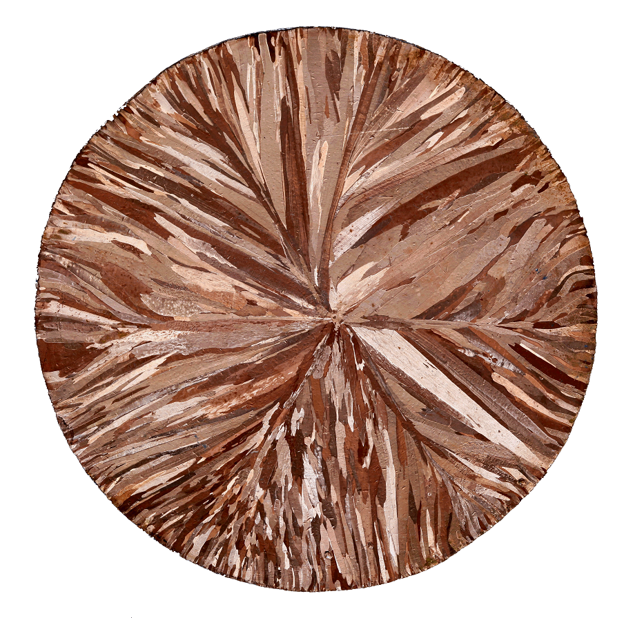
Most of the "single-crystal" wire in the audio business is made using the Ohno Continuous Casting (OCC) process which was developed by Atsumi Ohno of the Chiba Institute of Technology in Japan. The process employs a heated mold and drawing the solidifying copper from the mold at a very slow rate.
By this means, it is possible to cause the solidification process to start from the inside-out resulting in the formation of very long crystals in the metal, rather than the many short crystals which form in conventional casting when the material cools from the outside-in. In truth, the cable so produced is not mono-crystaline, but there are only a few crystals per metre of length.
Oddly it seems very hard to get hold of data on the resistivity (or conductivity) of wire produced by the OCC process.
From http://www.occmetal.com/ we find the following bewildering statement,
At present, our production of single crystal copper material can reach 99.99997% (6N) purity...... Single crystal copper wire electrical conductivity is 20% higher than that of the gold."
This is hardly a spectacular claim when normal ETP copper has a conductivity some 30% better than gold! Sadly, there are currently no official classifications for these specialty coppers and the IACS conductivity is not readily available, so it's difficult to know what these OCC copper products actually offer in terms of electrical performance.
Conductivity and micro-diodes
In any case, the argument for the superiority of single-crytal copper wire and silver wire is hard to reconcile with straightforward electrical conductivity. For high-impedance (small signal) work, even 7% change in conductivity is a very marginal change. Substituting a 10m silver cable for a copper cable in a balanced 600Ω terminated circuit, will cause a change in level of 0.2% (0.02dB) — a change well below the Just Noticeable Difference (JND) threshold for loudness change. In a circuit where one metre cables feeds a standard 10kΩ input impedance, the changes will be two order of magnitude smaller still.
We have to look to something more exotic to explain the differences audiophiles ascribe to these high conductivity cables.
A more subtle conjecture is that the crystals (and crystal boundaries or grain boundaries) which make up processed copper of all grades can impede current as the electrons cross the crystal boundaries. Even worse, that these crystal boundaries may act as miniature diodes (micro-diodes) with an inherent non-linearity which distort low-level signals. Thus cables with fewer crystal grain boundaries will distort the signal less. OCC cable is especially praised for its lack of crystal boundaries which might otherwise interfere with low-level signals.
It must be said that neither classical electron nor quantum-mechanical theories of electrical conduction allow for such an "micro-diode" effect (see Appendix). Nonetheless, a solid empirical study of this putative mechanism was understaken by Doug Self who describes the development of an ultra-low-noise amplifier system so that low-impedance passive components to be tested for nonlinear distortion at extremely low signal levels (0.01% on a 200µV signal).4,5,7
Self discovered no evidence of non-linearity in any of the components, including lengths of copper cables (of all types), tested at low levels. He says,
.....The results obtained are in a sense disappointing..... there are
no unsuspected low-level nonlinearities in components
likely to be used in audio systems. No new and intriguing
design problems have been set.4
........it would be nice to think that this red herring at least has been laid to rest.5
High-frequency effects
Lastly, the marketeers of analogue audio cables - when they are not obsessing wth conductor purity - often invoke descriptions of physical effects relating to the propagation of high-frequency signals in cables. The importance of high propagation velocity and the minimisation of skin effect are particular favourites.
The problem here is the confusion of the requirements for cables for digital audio signals and those for analogue audio signals. The subjects of transmission lines and skin effect and how they relate to digital and analogue audio signals are covered in the panel.
How the IACS Standard works
The International Annealed Copper Standard (IACS) establishes a standard for the conductivity of commercially pure annealed copper. The standard was established in 1913 by the International Electrotechnical Commission (IEC).
The IEC established that, at 20�C,commercially pure, annealed copper has a resistivity of 1.7241x10⁻⁸Ω-metre or 5.8001x10⁷ Siemens/metre when expressed in terms of conductivity.
For convenience, conductivity is frequently expressed in terms of percent IACS and all other conductivity values are related back to this standard value of conductivity for annealed copper. Thus, iron has a conductivity of approximately 18% of that of annealed copper and this is reported as 18% IACS.
Transmission lines
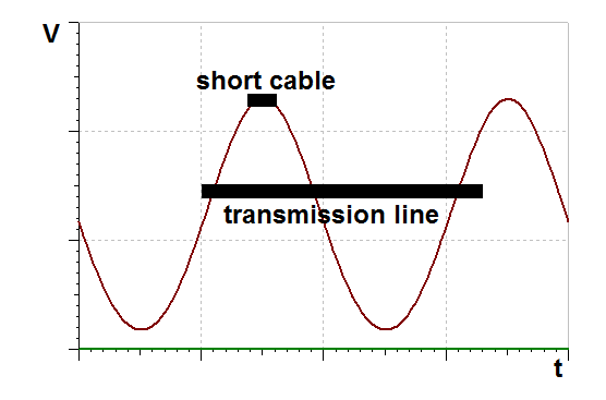
When an analogue signal is applied at one end of a short cable, we consider that, to all intents and purposes, the whole length of the wire is instantaneously at the same potential.
The short cable is like a small boat on the swell of the sea which simply bobs up and down on the wave. But a big ship, long in relation to the wavelength of the sea-swell, must plough through the waves.
Something similar happens when a cable is long in relation to the wavelengths of the signal frequencies it is carrying. The waves of current, which are the electrical signal, behave as waves along the length of the wire as they speed along it, and this creates a much more complex situation; as the gentlemen who invested vast sums of money laying the first trans-Atlantic communications-cable found out to their cost.
The cable didn't work because the cable was many times longer than the wavelengths of the signals it was intended to carry. We reserve the term transmission lines for cables in this condition.
It is common to see the theory of transmission-lines being applied to short, analogue interconnect cables which is misleading. The wavelength of a 20kHz signal in a coaxial cable is over 10km. Hardly a dimension to trouble the average vinylista!
The very short wavelengths of the signal frequencies in digtal audio mean that, even a short cable must be treated as a transmission line: it must be double-terminated and have a controlled characteristic impedance.
Skin effect
Skin effect is the tendency of an alternating electric current to collect towards the surface of an electrical conductor. It is due to eddy currents within the metal of the conductor which force the current away from the centre of the cable.
Skin effect causes the effective cross sectional area of the conductor to be reduced and thereby increases the metal's apparent impedance. In all metals, the depth of the concentration of the current (called the skin depth) falls with frequency. In copper the skin depth ranges from 9mm at 50Hz, to 0.65mm at 10kHz, to 0.02mm at 10MHz.
Skin effect is clearly only relevant when the dimension (diameter) of the conductor is significant in relation to the skin depth. The diameter of the inner conductor of a small-signal, audio cable is typically around 1mm, so it is clear that, whilst skin effect plays only a very limited rôle at analogue audio frequencies, it clearly has an important effect at digital-audio frequencies.
To mitigate skin effect, conductors may be silver-plated (to give the cables a silver "skin") to take advantage of silver's higher conductivity as the current is pushed towards the edge of the cable.
So, what does make a good cable?
If analogue audio cables aren't transmisson lines plagued with skin effects and low-level micro-diodes, does this mean that the type of thin audio cables ("audio bootlaces") you can buy at the airport and which come free with audio gear is the high-point of cable engineering?
The answer is no. Here are a few examples of applications in which an audio cable plays a significant part of the electrical circuit, and where, an inappropriate choice of cable can have a significant, deleterious effect.8
Low level, high impedance circuits. For example the cable carrying the output of a moving-magnet cartridge to the preamplifier where the wrong type of cable can introduce anomalous frequency-response issues at the top of the audio passband. At best, this may upset the tonal balance, and may even render quadraphonic needle-drops impossible to decode. What is needed here is a cable with low capacitance per unit length.
Digital audio circuits, where the cable must act as a transmission line — a cable with the correct characteristic (surge) impedance is required in this case.
Low level, unbalanced signal circuits, where the cable must have adequate screening to prevent hum. A dense, multi-stranded screen is required in this case.
Putting it together
The ideal cable would combine these attributes together. And we might add a few extra requirements. Thus, the cable should be:
Low capacitance,
Possess good screening,
Have a controlled impedance (ideally 75Ω for digital audio work).
Be small diameter, light and easy bent and routed (to make cabling more tidy).
Be reasonably attractive. Cables hardly add to the quality of our lives, so they may as well be as pretty as we can make them.
A dispiriting search!
❝.... The knowledge that a cable employs a conductor array or an electron tunnel or that its performance gives deeper silences and longer decays doesn't convey much useful information to us! ❞
We need a lot of cables here at Pspatial Audio as we develop Stereo Lab, and we need them both for low-level analogue signals and for post digitisation (SPDIF) digital signals. So, we looked for cables which would fulfil our five criteria listed above. A reasonable stock of these cables in the lab' could be pressed into duty without having to sort out appropriate types each time a cable is required.
We searched for a commercial product and, whilst there must be suitable cables in this crowded market which would fit the bill, we couldn't identify them. We looked at hundreds of cables from low cost examples on Amazon to items on specialist audio websites with prices ranging from a few pounds (GBP) to over £20,000 !
Product descriptions ooze apparently technical information but rarely offer any real insight into conductor configuration or useful electrical characteristics. And product reviews seems to concentrate entirely on the most informal of listening tests.
Sadly, the market influencers do not seem to share our urge to get out the wire cutters when asked to judge a cable. The knowledge that a cable employs a conductor array or an electron tunnel or that its performance gives deeper silences and longer decaysdoesn't convey much useful information to us9!
Dual-Mode™ Cables
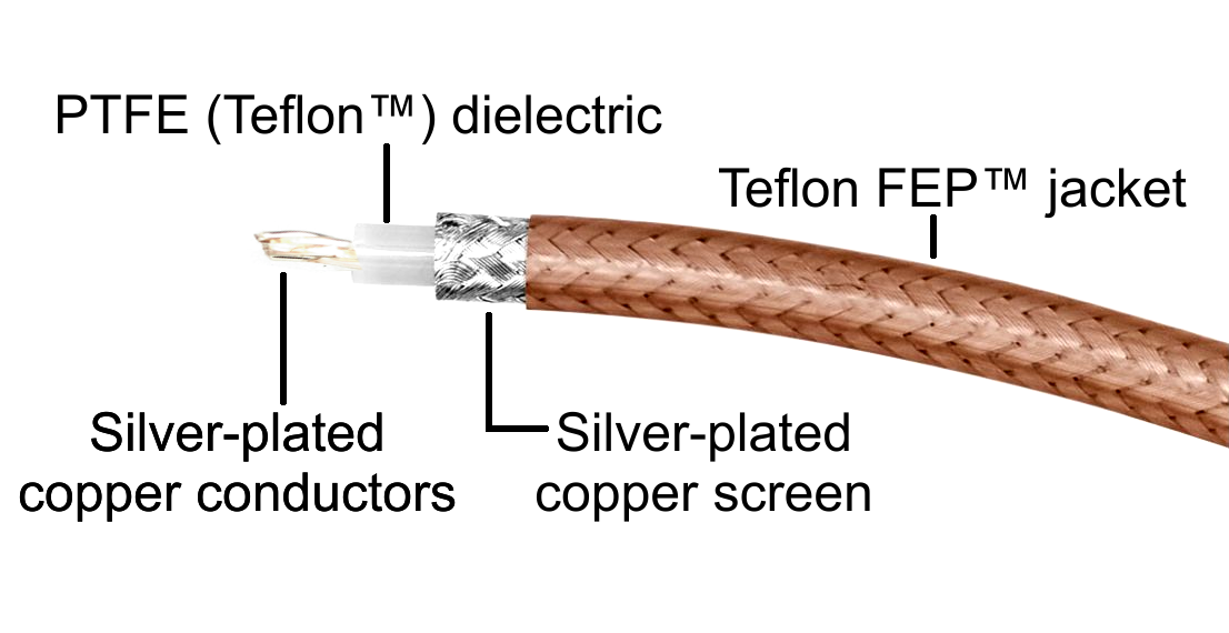
So, in the end - and with some reluctance, because making-up cables is fiddly and boring - we made our own. We chose a miniature, coaxial type cable with a central conductor of silver plated copper and a silver plated copper braid with a PTFE (Teflon�) dielectric.
Polytetrafluoroethylene (PTFE) has excellent dielectric properties � far superior to PVC or even polyethylene. The high quality of the dielectric enables the constructon of a small and light cable with excellent properties at high-frequencies.
The outer jacket of the cables is Teflon FEP� (Fluorinated Ethylene Propylene) a material which shares PTFE's useful properties of low friction contributes to the low mass of the cable (15g/metre) and to the excellent minimum bending radius of 10mm. The material is also transparent which means the attractive silver-plated screen is visible.
Until the arrival of quantum mechanics, electrical conduction was explained using the classical mechanics of Sir Isaac Newton (right).
When an electric field E is applied to a metal conductor, the electrons get accelerated by the force eE. From Newton�s second law, we can say,
m dv⁄dt = eE ............. (1)
Where, m, e and v are mass, charge and velocity respectively of the electron.
Now, keeping Newton first law in mind, we know that, once a force has been removed, a body will continue with constant velocity. So, we can say that, once the electric field has been removed, the electrons will carry-on moving and a current will keep flowing in the wire....
Whoops, something's wrong! We know current doesn't continue to flow once the electrical field has been removed, so what's happening?
Something must be impeding the movement of the electrons. We believe it is the collisions they make with the atoms in the crystal lattice. This is responsible both for the damping of the movement of the electrical current and for controlling it so that current doesn't go on increasing as the electrons are further and further accelerated by the electric field.
Just as there is a terminal velocity for a falling body in the earth's gravitational field as the force due to the air resistance balances out the gravitational force. So the resistive forces in the conductor balance out the force due to the electric field and put a limit on the current which can flow. Physicists call this constant drift speed (Vd): "terminal velocity" of the electrons if you like.
The resitive constraints on the accelerating electrons may be combined with equation (1) to create a differential equation which describes the motion of the electrons from which a term emerges (from the resistive part) which has the dimension of time. It is called the relaxation timeΤ and it represent the average time between consecutive collisions of an electron with a lattice atom.
This gives us the classical picture of electrical conductivity as being related to the number of free electrons per unit volume of the material (the population density) and the relaxation time.
We can combine the relaxation time (Τ) with the terminal drift speed (Vd) to calculate an important parameter in discussing electrical conduction which is known as mean free path (L) which is picturesquely speaking, the average distance an electron travels before it bumps into a lattice atom. In copper the mean free path is approximately 100 atomic spacings. It is calculated thus,
L = Vd × Τ
A couple of things to note about equation (1). There is no lower bound on the force eE. Charge e is a constant and Ee can go all them way to zero as a function of E (EMF). Neither is there any hint that, if E was to reverse (and become -E) because the poles of the EMF were to reverse, the current would flow the other way in exactly the same way. There is no hint of anything diode-like in this theory.
Quantum mechanical picture
Quantum mechanical explanations of electrical conductivity rest upon predictions from knowledge of electron population density and relaxation time just like the classical mechanical theory.
However, whereas the classical view is that all valence electrons contribute to conduction, the quantum mechanical view is that the number of electrons available for electrical conduction in a particular material is related to the arrangement of electron states or levels with respect to energy, and the manner in which these states are occupied by electrons.
In this analysis, the energy of the electrons is more fundamental than their position which is fortunate because, another of the great insights from quantum physics is that it is impossible ever to know both energy and position of an electron exactly (Heisenberg's Uncertainty Principle). The quantum view here is to concentrate on the electron energies and accept that their positions are wrapped in obscurity, represented best by a graph or an equation of probability.
The energy based model we use is known as Band Theory.
Band Theory
The electrons of a single isolated atom occupy atomic orbitals, which form a discrete set of energy levels. Atoms can neither absorb nor emit energy in a continuous fashion, the energy levels are said to be quantised. This is the very root of quantum theory which was derived from theories to explain observations of thresholds for certain physical effects which could not be reconciled with classical physics. One such is the photoelectric effect which identified, for a given metal surface, there exists a certain minimum frequency of incident radiation below which photoelectrons are not emitted.
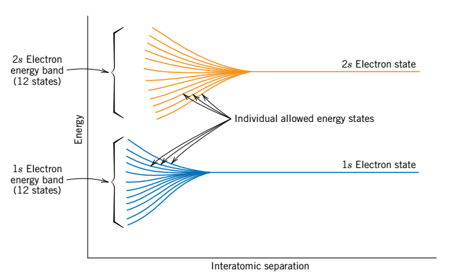
When several atoms are brought together into a molecule, the electrons are acted upon, or perturbed, by the electrons and nuclei of adjacent atoms. This influence is such the atomic orbitals split into separate molecular orbitals, each with a different energy. The illustration (right) gives a schematic plot of electron energy versus interatomic separation for an aggregate of 12 atoms. As the atoms apprach one another, each of the 1s and 2s atomic states splits to form an electron energy band consisting of 12 states.10
When a very large number of atoms are brought together to form a solid (remember that there are about 1023 atoms in one cubic centimetre of copper)13, the number of orbitals becomes huge and the difference in energy between them becomes very small. This is a key concept.
In solids, the energy levels form continuous bands of energy rather than the discrete energy levels of the atoms in isolation. The electrical properties of a solid material are a consequence of this electron band structure.
The arrangement of the outermost electron bands, and the way in which they are filled with electrons determines the behaviour of a material when subjected to an electric field.
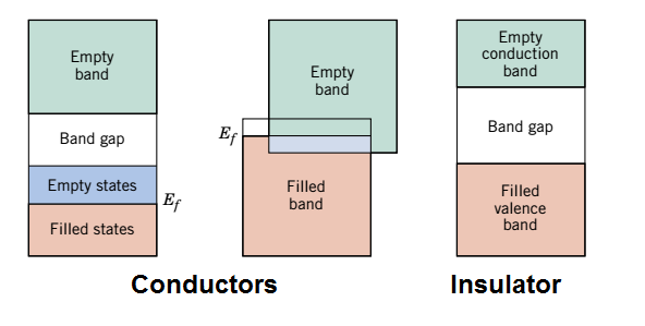
The electron band structure in various materials is illustrated left. The leftmost diagram and the central diagram illustrates the band structure found in metals, in which there are available electron states above and adjacent to filled states, in the same band.
The rightmost diagram illustrates the electron band structure characteristic of insulators; the filled valence band is separated from the empty conduction band by a relatively large band gap (>2eV). The electron band structure found in the semiconductors, is the same as for insulators except that the band gap is relatively narrow (<2eV).10
If we cool our conductor down to absolute zero (0°K or -273°C), we establish an important energy level, the so called, Fermi energy (Ef) which is the energy of the most energetic state of the electrons in the outermost band. This is illustrated in the diagrams. The Fermi energy for the insulator lies near the centre its band gap.
Back to conduction....and champagne!
The point of the dalliance into Band Theory and Fermi energy is because of a crucial part of quantum mechanical models of electrical conduction is that......
Only electrons with energies greater than the Fermi energy may be acted on and accelerated in the presence of an electric field. These are the electrons which participate in the conduction process and are termed free electrons.
For an electron to become free, it must be excited or promoted into one of the empty and available energy states above Ef. For conductors having either of the band structures shown, there are vacant energy states adjacent to the highest filled state at Ef. Thus, very little energy is required to promote electrons into the low-lying empty states. Generally, the energy provided by an electric field is sufficient to excite large numbers of electrons into these conducting states.10
The energy band diagrams given above are very tidy, with all the levels settled and with a precise Fermi energy. We can draw them like that because the diagrams (as stated) represent the situation at absolute zero temperature (0°K or -273°C).
Once we add some heat, the electrons have extra energy. This "dithers" the energy levels and the Fermi level so that, some electrons are promoted into electrical conduction without the need of an external electric field. This is the origin of thermal noise measured in all electrical conductors and which is inevitably added to any conduction current established via the poles of an EMF. In real materials at room temperature, electrons with an energy close to Fermi energy surface "fizz" - just like the spray of bubbles that forms above the surface of freshly poured glass of champagne (the ones that tickle your nose).
The quantum mechanical elaboration of classical theory is much better than the older classical theory because it modifies some predictions from classical theory which disagree with experimental results. For example, without the quantum mechanical modifications, classical theory predicts that magnesium will conduct better than copper (because magnesium has two valence electrons to copper's one).
Even in this more complicated theory, there is nothing to suggest that current flows better in one direction than the other at any level of applied EMF. No diode type effects are included in the model because none have ever been observed. Similarly, in a practical electrical wire comprising billions of trillions of atoms, the energy bands really are virtually continuous and in any case are "dithered" by heat energy. No threshold effect for metallic conduction is predicted.
Electrical properties of grain boundaries (and wave mechanics)
❝.... This may seem counterintuitive. Surely electrons will falter as they cross these grain boundaries like soldiers staggering across trenches dug into the battlefield...... The problem is that intuition is a very poor guide to anything at the atomic scale. ❞
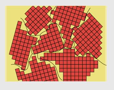
When thinking about crystalline solids like metals, we shouldn't imagine perfect order on a atomic scale.
Polycrystalline solids (which most crystalline solids are) are composed of a collection of many small crystals or grains. During the solidification of a polycrystalline material, small crystals or nuclei form. Because they are completely separate from one another, these nuclei have random crystallographic orientations.
The small grains grow by the successive addition from the surrounding liquid and maintain their original orientation. But, as the solidification process approaches completion, the extremities of adjacent grains must impinge on one another and, inevitably, the crystallographic orientation varies from grain to grain with an atomic mismatch within the region where two grains meet. This area is called a grain boundary.10 The endpoint is illustrated schematically by the red crystals in the diagram (right). The grain boundaries, as they appear under a microscope, are illustrated by the black lines.
The Band theory given above describes an idealised single crystal of material. The existence of the (almost) inevitable grain boundaries in real polycrystalline solids modifies the theory to introduce narrow energy bands in the forbidden band gap. As a very general rule, the introduction of these new bands tends to increase the conductivity of insulators and semiconductors and has surprisingly little effect on metals.11,12
This may seem counterintuitive. Surely it's obvious that in a grainy metal the "flowing electrons" will falter as they cross these grain boundaries like soldiers staggering across trenches dug into the battlefield.
The problem is that intuition is a very poor guide to anything at the atomic scale. Quantum mechanics tells us that electrons behave as both particle and wave. Resistance isn't due to little particles "bumping into" the atomic lattice (as we believed it was in classical mechanics). In fact, as Feynman points out14
the atoms are large, relative to their spacing, so that ...you would expect the electron to bump into one atom or another almost immediately. Nevertheless, .... if the lattice is perfect, the electrons are able to travel through the crystal smoothly and easily�almost as if they were in a vacuum..... In a radio tube electrons move freely through a vacuum, while in the transistor they move freely through a crystal lattice.14
Even in a perfect crystal, for the structure to be exactly periodic, the metal must be a zero temperature (that's why superconductors around an MRI machine must be kept as near as possible to 0° K). Heat disturbs the periodicy of even the most perfect crystal lattice, and this creates interference between the waves whereby the conducting electrons are continually having to give up the extra energy given to them by the applied EMF. This energy appears as heat but it isn't analogous to heat due to friction as electrical resistance is in classical theory.
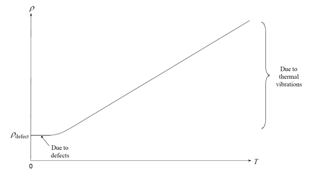
Understanding electrical conduction in terms of quantum (wave) mechanics helps us understand why the disruptions to the orientation of the lattice at grain boundaries isn't quite the problem that it intuitively seems to be from a classical mechanical viewpoint. Clearly grain boundaries have some effect on conduction, as the Korean study showed.³ But the influence upon conductivity of grain boundaries is greatly less important than the influence of impurities in the metal and the overwhelming influence of heat. Total resistivity ( ρ(T)) is related to temperature by Matthiesen�s rule:
ρ(T) = ρdefect + ρthermal
where the low temperature resistivity (ρdefect) depends on the concentration of lattice defects, such as grain boundaries.
References and Notes
1. A quick Google search will establish that this belief is indeed widely shared. However, it isn't universal. Where audio cables are concerned it seems it is open-season on almost any theory and opinion.
2. The Metallurgy of Copper Wire. Pops, H. Innovations (Magazine of the Copper Development Association) December 1997.
3. Copper Better than Silver: Electrical Resistivity of the Grain-Free Single-Crystal Copper Wire. Cho, Yong Chan et al. Crystal Growth and Design (periodical) April 2010 https://doi.org/10.1021/cg1003808
4. Ultra-Low-Noise Amplifiers and Granularity Distortion. Self, D.R.G. J. Audio Eng. Soc., Vol. 35, No. 11, November 1987. This article is required reading. The experimental design is excellent and the circuit design to achieve it ingenious. However, the article contains a stylistic misjudgement. In the results section, Self says, it would be tedious to relate a long series of negative results and avoids so doing. This ignores Bertrand Russell's wise words that, Some things are believed because people feel as if they must be true, and in such cases an immense weight of evidence is necessary to dispel the belief. The intervening thiry years proves Russell is correct. Self would have "served the cause" better had he included a long set of boring, negative results.
5. Audio Power Amplifier Design, Self, D.R.G. Focal Press 2013
6. The C10200 - Oxygen-Free (OF) copper standard requires 99.95% purity. It has a 0.001% oxygen content but its conductivity rating is no better than the more common ETP grade. C10100 grade copper (also known as Oxygen-Free Electronic or OFE copper) is 99.99% pure copper with 0.0005% oxygen content. In theory, the conductivity of C10100 grade is specified to be 1% better than ETP; although practical ETP coppers nowadays exceeds 100% IACS rating and achieves a conductivity as good as OFE. (Remember the IACS standard dates from 1913 and metal refining and processing has significantly improved over the last 100 years.)
7. It's worthwhile calculating the magnitude of a 0.01% distortion component of a 200µV signal. It's 20nV which is equivalent to the thermal agitation noise in a 1Ω resistance (about the resistance of a 1m of small-signal cable). Any lower and the distortion components would be buried in the thermal noise generated by the random movements of the electrons in the wire itself.
8. An additon to this list (but irrelevant here) is loudspeaker cables, where the cable must be very low impedance and where conductivity definitely does play a role. Even in double blind tests, it has been established that the resistance of loudspeaker cables play a statistically and psychoacoustically significant role. See: Speaker Cables: Can You Hear the Difference? Greenhill, L. Stereo Review August 1983.
9. Except that one suspects what is really behind this industry-wide, studied indifference to scientific method is the reluctance to admit the good-fortune to have stumbled upon a low-tech, zero-maintenance product with extraordinary profit margins which manufacturers have been canny enough to share with their sales channels and with influencers via their advertising-budgets. You can't expect to have much rational conversation at a party where the water has transformed itself into wine.
10. Materials Science and Engineering, 9th Edition SI Version (p. 684). William D. Callister Jr.. John Wiley & Sons Inc.
11. Electrical properties of grain boundaries. G. Lormand. Journal de Physique Colloques, 1982, 43 (C6), pp.C6-283-C6-292
12. The introduction of narrow energy bands in the forbidden band gap in polycrystal insulators due to grain boundaries tends to increase the conductivity of insulators which is why the very best insulators are not crystal — like glass.
13. The number of molecules in the gram molecular weight or 1 mole of a substance is called Avogadro's Number and equals about 6.022 × 10²³. The same number gives the number of atoms in a gram atom of an element. The atomic weight of aluminium 26.98 grams, so that 29.98 grams of aluminium contain 6.022 × 10²³ atoms.
14. The Feynman Lectures on Physics, Volume III - quantum mechanics. California Institute of Technology 1963
15. Named after Polish scientist Jan Czochralski who invented the method in 1915 while investigating the crystallization rates of metals. It is said that he made this discovery by accident: instead of dipping his pen into his inkwell, he dipped it in molten tin, and drew a tin filament, which later proved to be a single crystal.

 The belief that audio cables, if they can't be silver, must be of exceptional purity copper is widespread. This is justified in the case of the presence of other elemental metals which only need to be disolved in the copper in very low concentrations to affect radically its electrical properties.

.jpg)

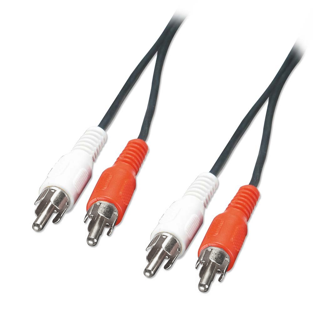 If analogue audio cables aren't transmisson lines plagued with skin effects and low-level micro-diodes, does this mean that the type of thin audio cables ("audio bootlaces") you can buy at the airport and which come free with audio gear is the high-point of cable engineering?
 So, in the end - and with some reluctance, because making-up cables is fiddly and boring - we made our own. We chose a miniature, coaxial type cable with a central conductor of silver plated copper and a silver plated copper braid with a PTFE (Teflon�) dielectric.
 When several atoms are brought together into a molecule, the electrons are acted upon, or perturbed, by the electrons and nuclei of adjacent atoms. This influence is such the atomic orbitals split into separate molecular orbitals, each with a different energy. The illustration (right) gives a schematic plot of electron energy versus interatomic separation for an aggregate of 12 atoms. As the atoms apprach one another, each of the 1s and 2s atomic states splits to form an electron energy band consisting of 12 states.10
 The electron band structure in various materials is illustrated left. The leftmost diagram and the central diagram illustrates the band structure found in metals, in which there are available electron states above and adjacent to filled states, in the same band.
 For an electron to become free, it must be excited or promoted into one of the empty and available energy states above Ef. For conductors having either of the band structures shown, there are vacant energy states adjacent to the highest filled state at Ef. Thus, very little energy is required to promote electrons into the low-lying empty states. Generally, the energy provided by an electric field is sufficient to excite large numbers of electrons into these conducting states.10