Many beautiful and important recordings were made in Quadraphonic, and versions of many classic recordings were mixed in Quad'. Decoding these recordings allows us to revisit old friends
...... I've been able to play with Stereo Lab for the better part of the weekend. Its SQ and QS decoding is superb, far superior to the Tate 101A and Sansui Vario-Matrix boxes, respectively. It's also superior to my Adobe Audition decoding scripts. It's just plain fantastic. Well done. - Doug Steenhuisen
In place of stereo's flat "wall of sound", Quadraphonic sound promised an immersive experience of music from all around the listener.... and all from the humble LP record!
George Orwell's Animal Farm taught us that two legs were bad, and four legs were good. The story of the failure of Quadraphonics in an almost parallel Orwellian tale of avarice and excess; as a lazy and greedy music-industry squandered this unprecedented era of good fortune to prove the same was not true with loudspeakers: two it seemed were good, and four were bad!
In effect, the rapacious labels tried to licence the technology to each other. A situation that clearly wasn't viable and resulted in a plethora of rival, and largely incompatible systems being developed rather than pay a competitor's licence fees. The result of course, was failure for all the systems. And a damning failure too; to the extent that "Quadraphonic" has now become a byword of nineteen-seventies excess and technical sleaze.
And yet, beneath the marketing veneer and the squalid business dealings, Quadraphonic sound was based on some genuine psychophysics and some very clever technology. And, as home-cinema proved thirty years later, the public do indeed have an appetite for "surround sound". Moreover many and important recordings were made in Quadraphonic.
 The challenge of encoding four channels of information on the medium of the LP record, which had only just been adapted to carry two stereo channels was not an inconsequential problem in 1970. It was solved in various ways: the two main approaches being:
 CD-4's high frequency carrier technique was borrowed from radio ideas. In theory, it provides true 4-channel replay. But the practical realisations involved pushing the performance-envelope of vinyl records to their limits. Despite considerable innovation in the development of special styli and manufacturing techniques, the records were easily damaged and wore out quickly. However, there still exist record-collectors who are fans of the CD-4 so, Stereo Lab supports the decoding of CD-4 recordings.
The other systems were based on phase-amplitude matrixing techniques. These systems all derive ultimately from a theory developed by mathematician and musician, Peter Scheiber. The easiest way to comprehend the ideas behind matrix Quadrophony is to consider the manner in which the stylus moves in a stereo record groove, as illustrated below.
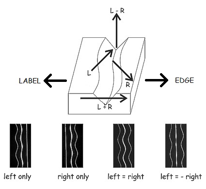
In a mono gramophone (phonograph) record, the music is captured in side to side (lateral) modulations of the groove. This is retained in a stereo record, but the extra stereo (channel-difference) information is modulated by supplementing the side to side "wiggles" of the mono signal with up-and-down (vertical) stylus movements. Scheiber and others realised that this process could be continued, with yet more, unique movements of the stylus employed to encode other signals, such as those as the rear channels of a 4-channel, or quadraphonic recording.
Another way to visualise this is with an audio X-Y display (sometimes called a Goniometer), which illustrates the stylus movements but rotates the view so that (L + R) information is displayed vertically and (L - R) horizontally. If an audio tone is panned from full left to full right, the resulting display on the Goniometer is as shown below.
.png)
Clearly this panned signal has occupied all the stereo soundstage, yet it has not occupied all the "space" displayed on the Goniometer display. In fact two entire quadrants are unused. It is in these quadrants that the extra signals are "hidden" in a Quadraphonic system. Scheiber and others developed many different systems, all of which were based on variations of this theme. Systems based on hiding signals in this way are called Regular Matrix systems. The QS quadraphonic system was developed by engineer Ryosuke Itoh of Sansui is a phase matrix system, as is EV Stereo-4 and Dolby Surround.
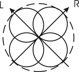
Other systems, like the successful SQ system developed by CBS in New York, use even more cunning arrangements such that the rear channels are encoded by circular movements of the stylus (actually helical, because the circles are unwound as the record is turning). This is accomplished by feeding the rear signals through phase-shifting networks (called Hilbert Transformers) so that all the frequency components are in phase-quadrature. The resulting signals are thereby complex. By arranging one of the rear signals to create clockwise circular movements, and the other to create counter-clockwise movements, perfect separation is achieved between the rear channels.
If an SQ signal is displayed on an X-Y audio display, the circular modulation is clearly visible.
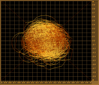
Here right-back modulation in the SQ system is displayed on an audio goniometer. The circular modulation pattern is clearly visible. (The Goniometer reflects the movements of the stylus but tilted over 90°.)
Unfortunately, you only have to think of a crankshaft in a car engine to realise that circular movements still have substantial side to-side and up-and-down components and this accounts for the poor separation in the SQ system between front and rear channels. All the variations of Quadraphonic matrix systems: QS (Quadraphonic Sound)/ RM (Regular Matrix); EV / Stereo-4: DY / Dynaquad; Stereo UHJ and so on, all come down to the differing trade offs made between the perfect separation of the various fully complementary stylus movements and the crosstalk caused by similar stylus movements.

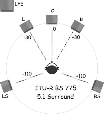
Stereo Lab provides accurate decoding of SQ and QS recordings so that they can be played over a modern 5.1 system - as defined in ITU-R BS 775 and illustrated below (although better results are obtained if the angle between the surround loudspeakers is reduced).
Visit Phædrus Audio's Listening Room to hear a demo of QS decoding in Stereo Lab.
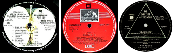
 A large quadraphonic discography exists encoded in the CBS SQ format which was introduced in 1972. This format is in third position after Dolby and QS. Many thousands of records are still available in this format in thrift store record bins. Record companies who adopted this format included: Angel, Capitol, CBS, CTI, Columbia, EMI, Epic, Eurodisc, Harvest, HMV, Seraphim, Suprophon, and Vanguard.
The early days of SQ were marred by the fact that early SQ decoders couldn't produce more than 3 dB of separation from front to back. A later enhancement was incorporated which implemented a channel blend in which rear-channel separation was traded for better front-back separation. Known as the 10-40 SQ Blend Decoder, this is the type of decoder implemented in Stereo Lab.
Or the output may be encoded as a multi-channel, 5.1 file. Note that, because these signals are Quadraphonic (four-channel), the Center and LFE channels are silent.
 The British Ambisonics recording and reproduction system also grew out of the heady success of the record industry in the nineteen-seventies. Brainchild of various British academics including the late mathematician Michael Gerzon, Ambisonics builds upon Blumlein's work to create a theoretically complete system for the acquisition, synthesis and reproduction of enveloping sound fields from a limited number of loudspeakers. One might say, Ambisonics is the thinking man's Quadraphonics!
A full treatment of Ambisonics theory is given in Pspatial Audio's Ambisonics White Paper. A short and simple account is given below.
Consider a sound-field disturbed by a single sound source. The sound is propagated as a longitudinal wave which gives rise to a particle motion along a particular axis drawn about a pressure microphone placed in that sound-field. Such a microphone will respond by generating an output voltage which is proportional to the intensity of the sound; irrespective of the direction of the sound source. Such a microphone is called omnidirectional because it cannot distinguish the direction of a sound source. If the pressure microphone is replaced with a velocity microphone, which responds to the particle motion and is therefore capable of being directional, the output is proportional to the intensity of the sound multiplied by (cos θ), where θ is the angle between the angle of the incident sound and the major axis of the microphone response.
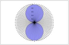
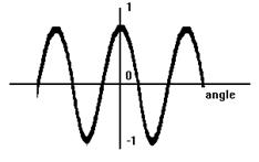
Directional response of one cosine (figure of eight) microphone (left) and the cosine function (right) which is negative in the second and third quadrants.
But there is an ambiguity as to the sound source's direction if the intensity of the signal emerging from a velocity microphone is considered alone. As θ varies from 0° to 359°, the same pattern of sensitivity is repeated twice over. On a practical level this means the microphone is equally responsive in two symmetrical lobes, known as the figure of eight response. Mathematically put, this is because the magnitude of the each half-cycle of the cosine function is identical. But not in sign; the cosine function is negative in the second and third quadrant. So, this extra directional information is not lost, but is encoded differently; in phase information rather than intensity information. What is needed to resolve this ambiguity is a measure of reference phase to which the output of the velocity microphone can be compared. Just such a reference would be provided by a pressure microphone occupying a position, ideally coincident but practically very close to, the velocity type.
More intuitively stated: a velocity microphone sited in a sound-field will resolve sound waves along (for instance) a left-right axis but not be able to resolve a sound from the left differently from a sound from the right; the addition of a pressure microphone would enable the latter distinction to be made by either subtracting or adding the signals from one another. Now consider rotating the velocity microphone so that it faced front-back. This time it would resolve particle motion along this new axis but would be equally responsive regardless of whether the sound came from in front or behind. The same pressure microphone would resolve the situation. Now contemplate rotating the microphone again, this time so it faced up-down, the same ambiguity would arise and would once more be resolved by the suitable addition or subtraction of the pressure microphone signal.
Consider placing three velocity microphones each at right angles to one another (orthogonally) and, as nearly as possible in the same position in space. The combination of signals from these three microphones, coupled with the response of a single omni-directional, phase-reference microphone, would permit the resolution of a sound from any direction. Which is the same thing as saying: a sound in a unique position in space will translate to a unique combination of outputs from the four microphones. These four signals (from the three orthogonal velocity microphones and the single pressure microphone) are the four signals which travel in the four primary channels of an Ambisonics recording.
In practical implementations, the up-down component is often ignored, reducing the system to three primary channels known as W, X and Y, where W is the omnidirectional signal, X is the frontwards signal, and Y is the leftwards signal.
The Soundfield microphone - rotated to reveal the similarity between this arrangement and four cardioid microphones arranged 90° to one another. This arrangement is the one used by the BBC for their Quadraphonic recordings.
If we consider the de-facto four speaker arrangement and limit the consideration of Ambisonics recording to horizontal plane only (three-channel Ambisonics), it's possible to consider rotating the velocity microphones so that, instead of facing front-back, left-right as described above, they face as shown in the figure above; an arrangement which is identical to Blumlein's crossed-pair.
If we label one microphone L, the other R, and the third pressure microphone P as shown.
By a process of simple addition and subtraction, four signals are obtainable from the combination of these three microphones;
(L + P), (L - P), (R + P) and (R - P).
Each one equivalent to a cardioid microphone facing diagonally left-front, diagonally left-back, right front and right rear, each pointing to one of the four cardinal positions occupied by the loudspeakers on replay. This approach is equivalent to the BBC's policy on Quadraphonic recording. Ambisonics theory has enabled the construction of special Ambisonics pan-pots which enable sounds to be artificially positioned anywhere in a 360 degree sound-stage based on simple channel-intensity ratios.
The three signals of horizontal-only Ambisonics may be combined in the form of a two-channel, compatible stereo signal in a process called Stereo UHJ coding although this process is lossy. This uses the same matrix technology which was developed for Quadraphonics. (In fact, the HJ in UHJ refers to Matrix HJ which is a matrix quadraphonic system developed by the BBC.)
Many important and beautiful recordings have been made in Stereo UHJ format; including almost the entire catalogue of the excellent UK based Nimbus record company. For this reason, Stereo Lab provides a high-quality decode of Stereo UHJ encoded recordings.
Ambisonics theory allows for various types of decoders (each optimised for some aspect of replay performance as explained fully in the Pspatial Audio's Ambisonics White Paper).
Five types of decoders are provided in the Stereo Lab software. The decoder type is selected on the Settings dialogue.
The first four options are for regular speaker layouts in a square. If you want to play these over a modern 5.1 system (as defined in ITU-R BS 775 and illustrated above), better results will be obtained if the angle between the surround loudspeakers is reduced. The four options are:
A further option is provided. This is Wiggins' solution to 5.1 optimisation1 and is called,
If this latter option is selected, the speakers may be left in their standard arrangement for 5.1 surround sound. The input file should be simple, two-channel stereophonic. The output may be selected to be separate mono files (useful if you want to re-encode in DTS for example), as a group of stereo files encoded:
Or the output may be encoded as a multi-channel, 5.1 file. Note that it is deliberate that the Center and LFE channels are silent.
1Wiggins, B. (2008), Has Ambisonics come of Age?, Proceedings of the Institute of Acoustics, Vol. 30, Pt. 6.
Home page
For all support issues, go here.
For Pspatial Audio sales, email: sales@pspatialaudio.com