
![]()
The following is mostly based on Ben Bauer's 1945 article1. Whilst lacking the formalism of Baerwald2 or the long ignored Löfgren paper3, Bauer's derivation is simpler and practical. Details of how to refine Bauer's results is given in the notes4.
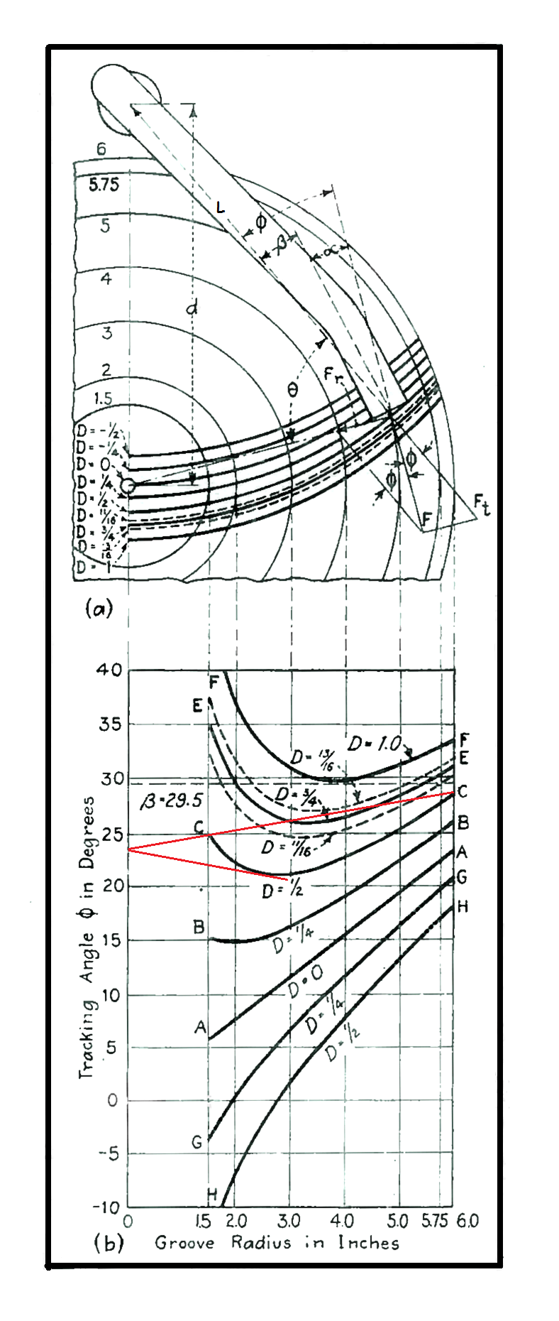
Let a tonearm having an effective length L (distance from the centre of the pivot to the stylus tip) be mounted on a plinth with its pivot d away from the centre of the record, as shown in the illustration left: where θ is the angle included between the lines L and r, and φ is the tracking angle between L and a line tangent to the groove at the needle point. The dimension D is the swing of the stylus point beyond the centre of the turntable. This is sometimes called overhang.
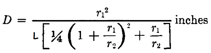
Solving for φ like this,
where φ is in radians. We multiply this by 57.3 to obtain φdeg to get the tracking angle between L and a line tangent to the groove in degrees.
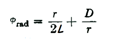
Figure (b) shows graphically the values of φdeg as a function of the radius for a 7½-inch arm and for various values of arm overhang D. (This illustration is taken directly from Bauer's article, hence the Imperial units and the slightly shorter arm than is typical today.)
These curves are very revealing, however it is easy to be confused by this graphic because in the drawing above (a) the tonearm is shown bent. In fact, these curves relate to a straight tonearm with various degrees of overhang.
The custom in the early days of the gramophone (phonograph) was to use straight tonearms pivoted in such a manner that the needle point passed through the centre of the record. The tracking angle corresponding to this condition is represented by curve A-A for D = 0.
Reading off the graph (right click for a larger image), we can see that the tracking angle between L and a line tangent to the groove in degrees at the 5¾-inch radius is 22°. This gradually decreases to 7.6° at the inner radius of 2 inches, a change of over 14°.
This led to a study of curves similar to those of Fig. (b) which indicated that the remedy might lie in swinging the arm beyond the centre of the record. By so doing, as curves B-B, C-C and E-E indicate, the progressive linear change in tracking angle of the non-overhung arm is transformed to a dished-curve in which the tracking angle decreases and increases over the working radii of the disc. True, the average error is increased each time. For example curve E-E has an average angle of 30°. But this can be accommodated by cranking (bending) the tone arm so that the tracking error (defined formally below) is reduced to a few degrees either way.
As an example, if the stylus point overhang D is 13/16 inch as for the dotted curve adjacent to E-E, the tracking angle varies from 32° at a 6 inch radius, through 27° at 3.3 inches, and back to 32° at the 2 inch radius. Now, if the pickup head is bent at a 29½° angle, the departure of the stylus from tangency is reduced to only ± 2.5°.
The difference between the tracking angle, φ and the offset angle β, has been termed tracking error and is designated the symbol α. Tracking error indicates how short of perfection the arrangement is.
For several years the pure goal of selecting an alignment so that the tracking angle departed least from an average angle (to which the crank was set) was considered the holy-grail of tonearm design. That was until Löfgren and Baerwald considered the mechanisms behind distortion of the audio signal due to tracking error.
An approximation of harmonic distortion (Hd) caused by a tracking error of α is,
Hd ≈ (ω . A . α ) / (ωr . r )
In which ω is the (angular) frequency of the modulation, A is amplitude, ωr is the angular frequency of rotation (i.e. the "speed of the record in radians/sec) and r is the radius of the groove. For those interested in the derivation of this expression, see the references. Also see note. 7.
This important equation reveals a great deal. Distortion is directly proportional to the amplitude and frequency of the modulation. It is also directly proportional to tracking error. No surprises there. However, it also reveals that tracking distortion is inversely proportional to the speed of the record and to the radius of the groove. Thus distortion due to tracking distortion is greater towards the centre of the record where the stylus is passing more slowly in the groove. And it is worse the slower the record turns. It's easy to see why the birth of the LP (turning at 40% of the speed of the 78 RPM record) rekindled concerns to reduce tracking distortion to a minimum.
In fact, for a given modulation amplitude and frequency and a given record speed,
Hd ∝ α / r ......... equation A
And so the problem becomes chosing a tracking angle (φ) curve (like those in Fig. b) which fulfils the condition that α / r is minimised at all radii.
Bauer reveals that, if two lines can be drawn from the y-axis (the "zero-inch ordinate") so that the φ curve is bounded by two lines of equal and opposite slope, then the overhang figure is ideal and the point on the y-axis indicates the β for minimal distortion at all radii.
Two red lines are drawn in this way on the illustration on this page which indicate that this condition is very nearly fulfilled in the case of curve C-C. (Equally, it's easy to see that similar lines could not be constructed for any of the other curves in the figure.) Indeed alignment C-C is very close to the optimum alignment. (An overhang D of 0.56" gives the optimum solution.)
It worth taking a moment to consider what Bauer is doing here. What equation A is telling us is that (other things being equal) distortion is proportional to tracking error weighted by the inverse of groove radius. More tracking error is permissible for a certain distortion threshold at the outer edge of the disc than it is at the centre.
Considered in the way we can see why Bauer's graphical hairpin method works. By the simple means of selecting the tracking angle (φ) curve which fits into the hairpin which is narrowest towards the zero-inch ordinate, we are selecting a range of tracking errors which best fulfils the condition that progressively less tracking error is tolerated towards the centre of the record.
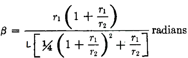
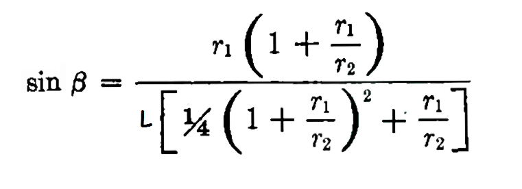
Bauer, having derived solutions for the best choice of position of tonearm of a given crank angle and effective length graphically, then derives design equations from the graphical constructions. Here is Bauer's final equation for overhang,
Where r1 and r2 relate to inner and outer groove radius limits respectively. This is labelled inches, but works for any other measurement unit, for example millimetres, provided the values of radii and effective tonearm length are input in millimetres. (In other words, any units may be used provided their use is consistent.) Note that d in the main figure (which is what you need to know when fitting a tonearm with known or measured L and β) is given by,
d = L - D .
And here is Bauer's equation for calculating offest angle in radians. Multiply by 57.3 to get β in degrees. (Note that β is measured clockwise from the line connecting the stylus point with the pivot point. It is not, as it is sometimes erroneously assumed, the angle between the body and the head of the tone arm.)
With the benefit of precise dimensional standards denied Löfgren, Baerwald and Bauer in the nineteen-forties, we can reduce these unwieldy expressions in r1 and r2 to constants and produce the, almost trivial, relations,
D = a / L ,
and,
β = b / L
where a and b are simply constants.
In practice, these equations give a slightly different solution to those proposed by Löfgren and Baerwald and technically give slightly higher distortion. However, they may be used for precise design with a couple of simple provisos.4
The great advantage of these simple expressions is that they foster a more intuitive appreciation that, for a given L, D and β, there exists an optimal solution. Their simplicity also makes it easier to visualise how the expressions may be manipulated to solve, for example, for D knowing β such that,
D = a/b × β
Even the enthusiastic vinylista really need never know or use these equations above. When fitting a modern tonearm to a turntable, the tonearm manufacturer, knowing the bend angle and effective length of the arm and fully understanding the alignments of Löfgren and Baerwald, will always specify the distance of the centre of the tonearm pivot mounting to the spindle centre to guarantee the optimum geometry. Nothing could be simpler. By applying the mathematics, the manufacturer has done the "heavy-lifting" for us. All the enthusiast need do is to make one measurement.
Similarly, in the case of a turntable with a fitted tonearm, it should only be necessary to specify the effective length of the arm from pivot to needle-point (dimension L) to guarantee the correct geometrical alignment when fitting a cartridge.
But just as a perfect answer seems to be available, disaster befalls us. Because no standard exists to define the stylus tip from the mounting lug centres of a phono cartridge, it forces most tonearm manufacturers to provide mounting slots so that the cartridge may be shuffled forward and backwards in its mountings. Thus the effective length (L) of the arm becomes undefined, the user able to adjust this by perhaps ± 5mm. And, because the slots allow one side of the cartridge to sit forward or rearward of the other, the cartridge may be skewed and thus the offset angle (β) may be modified by as much as a horrifying ± 30°.
"The slotted head-shell reduces all the clever mathematics
and engineering precision to dead-reckoning and optimism."
All the precision equations and engineering, the arguments as to the choice of Baerwald or Blauer alignments, calculations of L and β in mm to two points of decimals and the CNC manufacture of precision tonearms are mocked by the addition of cartridge-mounting slots. They invalidate the benefits of the theoretical work described above and force upon the user the need to align the cartridge visually using a tracking-angle alignment-protractor, a fiddly procedure.
A tracking-angle alignment-protractor is a plastic or paper template onto which are printed the null point(s)6 and lines of tangency against which the cartridge should be aligned (see left). The template is placed over the turntable's spindle (made possible via a spindle-sized hole in the template) and placed on the platter like a record. The stylus is then placed on various points on the template and the cartridge twisted and shuffled forward and back until it is parallel with the sets of parallel lines on the protractor. The concept is that, when the cartridge's longitudinal axis is parallel with the tangential lines at the null-points, tracking error will be at a minimum for the chosen alignment.
Even when the cartridge body has parallel sides this is a difficult adjustment to make with confidence as the diminuative cartridge body makes the judgement of tangency awkward. Many cartridges don't have parallel sides in the interests of a more striking aesthetic design, and these are almost impossible to align with confidence. Moreover, once the cartridge has been wiggled into what is judged to be the correct position, the mounting slots allow the cartridge to twist as the first securing bolt is tightened, forcing further iterations of the procedure. This is especially true if the bolts require nuts to be held whilst tightened.
The sadness lies in that all of this ought to be unneccessary. A properly designed tonearm, properly installed, only requires that the cartridge is set so that the stylus point is at a defined dimension from the tonearm pivot (the, so called, effectve length L). The slotted head-shell reduces all the clever mathematics and engineering precision to dead-reckoning.
Our recommendation for a cartridge-alignment protractor which offers: all the common alignments, a universal scale for checking parallelism errors over the entire recorded surface as well as offering practical design equations is available from Phaedrus Audio.
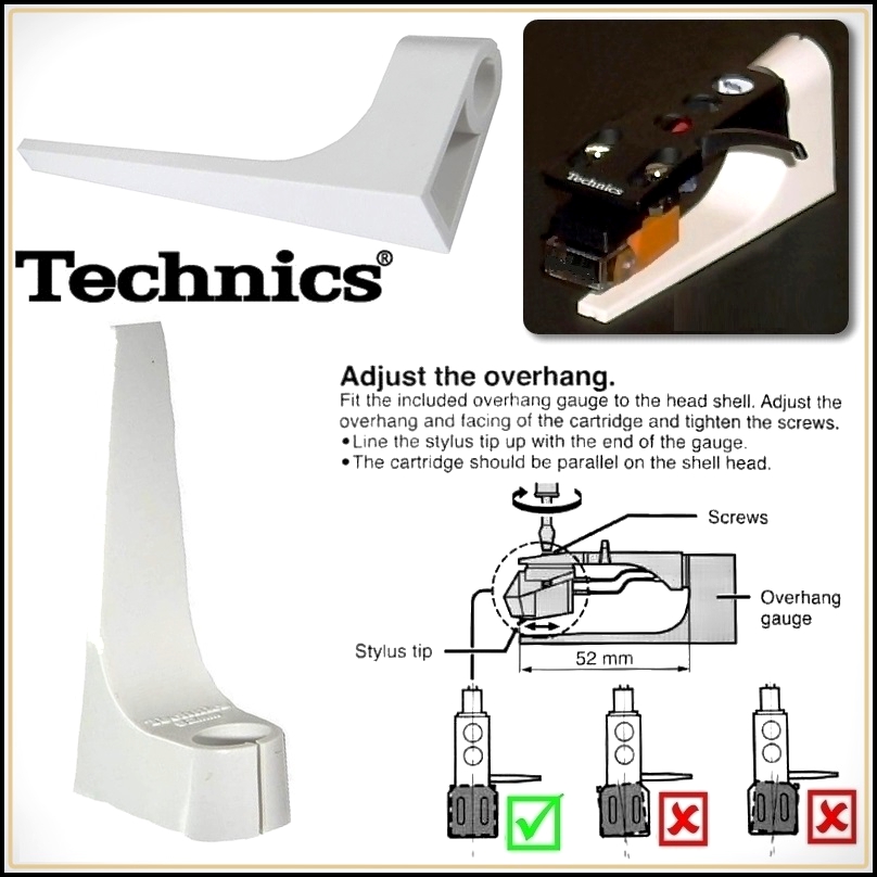 For the SL-1200 family of turntables, Technics produce a little set-up jig (called an Overhang Gauge) which may be used to set cartridge alignment without the use of alignment protractors etc..The removable head-shell is fitted into the Overhang Gauge jig and the needle-point set to be exactly parallel with the edge of the jig (with the cartridge full square in the headshell). This alignment assures that the effective length of the arm is as the designer intended 8.
This little tool is tremendously useful. Cartridges may be fitted and aligned away from the turntable where visibility is often better and where careless handling is less likely to cause expensive accidents. More manufacturers ought to consider this type of set-up jig. Even for tonearms with a fixed cartridge mountings (without separate head-shells), it ought to be possible to devise some template or jig to indicate the position the stylus tip must sit for the arm to possess the correct effective length. This would be greatly preferable to working with alignment protractors.
1. Tracking Angle in Phonograph Pickups. Bauer, B.B. Electronics March 1945
2. Über die nichtlineare Verzerrung bei der Wiedergabe von Schallplatten infolge Winkelabweichungen des Abtastorgans. (in German) Löfgren, E. Akustische Zeitschrift, Vol.3, November 1938. (Löfgren offered a complete solution many several years before the Baerwald paper. His analysis has never been surpassed.)
3. Analytical Treatment of Tracking Error and Notes on Optimal Pickup Design. Baerwald, H. G., Journal of the Society of Motion Picture Engineers, XXXVII. Dec., 1941.
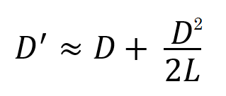
4. Bauer made two simplifications to the geometry in his article which was written to be a practical piece to educate manufacturers to adopt the work of Baerwald in their designs. One is that, at small angles sin β ≈ β (when β is expressed in radians). This was understandable in the days before electronic calculators, but is less comprehensible now. In fact, the errors this introduces are quite small - about 1% error for an angle of 23°. But, it is better to take his expression for β to be,
The second simplification was to ignore an expression for D² in his working. Bauer reasoned that, D² << 2.L.D and could therefore be ignored.
Once again, in the days of slide-rules, this was entirely justified because the errors introduced are quite small: but is less so today. Seagrave5, derived a correction-factor to Bauer's expression for D such that, a better approximation for overhang (D') is obtained if Bauer's solution (D) is applied to the following equation. This correction-factor typically adds about ½mm - 1mm to the overhang measurement.
5. Minimising Pickup Tracking Error. Seagrave, J.D., Audiocraft Magazine, Part 1, Dec. 1956; Part 2, Jan. 1957; Part 3, Aug. 1957.
6. Because the φ curve is "dished" there are clearly two points at which the chosen offset angle intersects the curve exactly. These are termed null-points and these are the two radii at which the cartridge should be aligned so that the axis of the cantilever is exactly parallel with the groove tangent.
7. Plugging real values into the expression,
Hd ≈ (ω . A . α ) / (ωr . r )
for 33⅓ RPM (= 3.49 radians/sec) records with a (standardised) innner radius of 60mm modulated with a 250Hz sinewave to a maximum modulation of 38µm pk (27µm RMS) leads to the following useful rule of thumb:
The distortion in %THD ≈ αdeg ÷ 2. So that, a tracking error of 5° will lead to THD of approximately 2.5% at the innermost groove on a 250Hz tone at maximum modulation.
Distortion at the outer edge of the disc is approximately 40% of that at the innermost groove. A full 6° of tracking error is required to cause 1% distortion on an outermost groove spiral (on our 250Hz example). Given this information, it's easy to appreciate that, if the proper geometry is observed, it is quite possible to reduce lateral tracking distortion to levels where it is insignificant compared with other distortions present in record replay.
8.
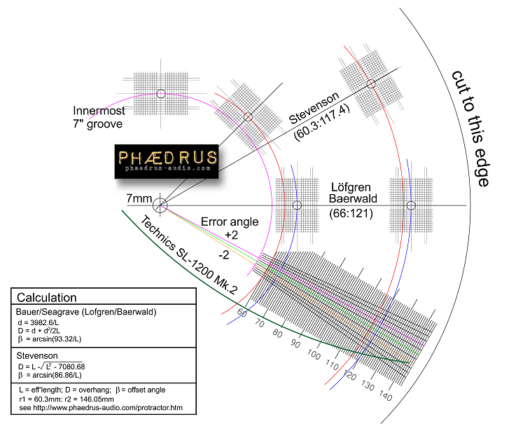
![]() Specifications of the tonearm for the Technics SL-1200 Mk.2 are: effective length 230mm; overhang 15mm; and offset angle 22°. This alignment chosen by the Matsushita engineers was not Löfgren /Baerwald. Instead the alignment concentrates on minimising the tracking error near the innermost groove. This approach is sometimes attributed to Stevenson (after Stevenson, J.K., "Pickup Arm Design", Wireless World May, June 1966). As the workings in note. 7 show, this is not a imprudent approach.
Specifications of the tonearm for the Technics SL-1200 Mk.2 are: effective length 230mm; overhang 15mm; and offset angle 22°. This alignment chosen by the Matsushita engineers was not Löfgren /Baerwald. Instead the alignment concentrates on minimising the tracking error near the innermost groove. This approach is sometimes attributed to Stevenson (after Stevenson, J.K., "Pickup Arm Design", Wireless World May, June 1966). As the workings in note. 7 show, this is not a imprudent approach.
Bauer's curves are redrawn (right) for the Technics tonearm. The Löfgren /Baerwald (Bauer) alignment is shown (blue curve complete with Bauer hairpin) and the Technics alignment is shown (yellow curve). Reading off this graph we can, once again, substitute real values into the expression for 33⅓ RPM (= 3.49 radians/sec) records, modulated with a 250Hz sinewave to a maximum modulation of 38µm pk (27µm RMS),
Hd ≈ (ω . A . α ) / (ωr . r )
The worst tracking error is at the outer edge of the disc (≈150mm) where the error is +2°. This leads to less than 0.5% THD. The other point of major tracking error is at r = 80mm where the error is about -1°. Substituting this data in the equation for THD reveals a very low 0.3%.
If the Löfgren /Baerwald alignment is adopted for the Technics SL-1200 Mk. 2, the cartridge must be moved quite a long way (≈ 3mm) forward and skewed ≈ 2°. This results in three points of maximum distortion due to tracking error (r ≈ 60mm, 85mm and 150mm) where the distortion rises to around 0.7%. There is thus no evidence that a Löfgren /Baerwald alignment is preferred to that obtained using the Technics Overhang Gauge jig.
Pspatial Audio Home page
For all support issues, go here.
For Pspatial Audio sales, email: sales@pspatialaudio.com