
Some of these exchanges are based on various misconceptions. This page sets out Pspatial Audio's understanding of vertical tracking error in phonograph records and our recommendations. We also take a look at the fashionable parameter of Stylus Rake Angle (SRA).
An audio demonstration of simulated vertical-tracking distortion is provided so that you can make up your own mind about the importance of VTA on distortion.
 The introduction of stereo records complicated both the design of the mechanical cutters used to engrave the groove information on the original lacquer disc and the design of the phono cartridges designed to read this extra information.
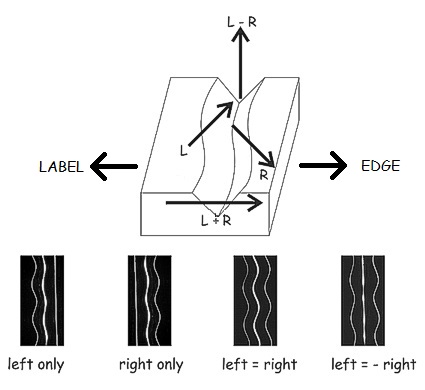
In addition to lateral movements of the groove, which contain the mono information, a stereo disc includes vertical modulation of the groove depth which contains the difference information that sorts the mono information into the left and right channels.
To transduce the groove modulations accurately into electrical signals in the pickup, clearly the pickup must follow - as nearly as possible - the path of the recording cutter. One problem which was discovered very early in the development of the gramophone, is due to differences in the path of the recording cutter head, which is driven in a straight-line across the radius of the disc by a worm gear arrangement, and the cartridge which moves in an arc at the end of freely pivoted tone arm. This results in the widely discussed, so called, lateral tracking error.
Vertical tracking error has many similarities with lateral tracking error and it shares the same mathematical analysis. But there is one major difference. Lateral tracking error arises purely on playback. Whereas, the origins of vertical tracking error lie in the mechanics of the disc cutting system in which it is impractical to design a cutter system to have a vertical modulation angle of 0°, since this would require the pivot point of the moving system of the cutter to lie in the plane of the record.
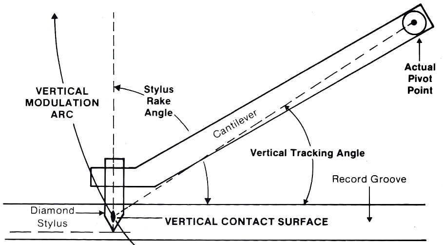
Instead, the cutting stylus must itself have a pivot above the disc's surface and the modulation cut into the lacquer must have a modulation angle with respect to the plane of the record surface. This angle is called the Vertical Modulation Angle (VMA) and, from the earliest days of the gramophone, this angle was set to be about 15°.
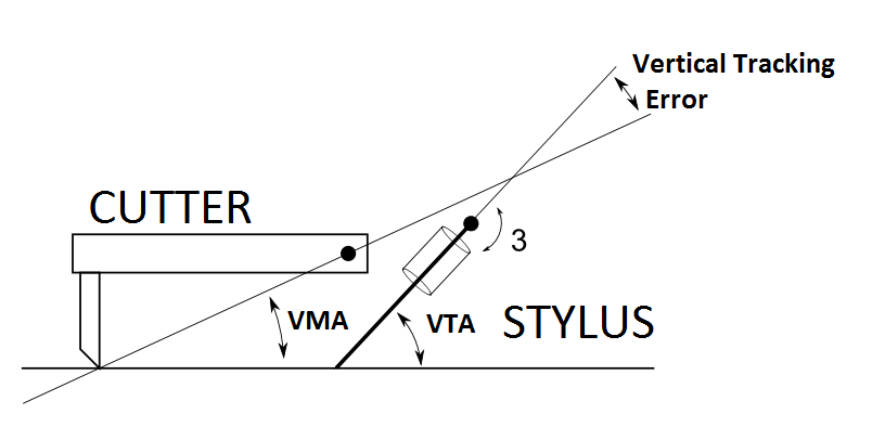
Mathematical analysis reveals that, provided this tilted modulation is read with a phono cartridge with a moving system tilted by the same angle as the cutter with which it was engraved, the modulation may be extracted with no error. So, it would seem this should present no problem at all. Because, just as with the cutter, it would be impractical to design a phono cartridge in which the pivot point of the stylus cantilever lay in the plane of the record anyway. All that is required is that it be agreed upon that VMA and the tilt of the phono cartridge moving-system (called the Vertical Tracking Angle or VTA) be standardised.
So it was believed with the invention of stereo discs. It was during later work that problems surfaced which revealed that matching VMA and VTA was a more complicated and difficult affair. The difference between the two angles being termed, vertical tracking error as illustrated in the diagram above.
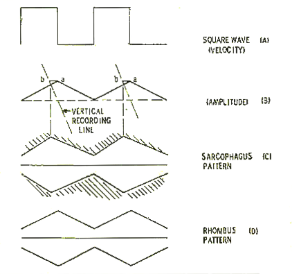
In the early nineteen-sixties, CBS Labs were evaluating the transient response of phono cartridges and needed a waveform inscribed on the disc which possessed two, opposing constant-velocity values. In other words, a triangular ramp in which the stylus would move in one direction at a constant velocity and suddenly switch to an equal velocity in the opposite direction. (A velocity-sensitive pickup outputs the time-differential of the groove modulation amplitude and outputs an electrical square wave.) In the vertical axis, a ramped groove would narrow and widen so that the stylus would rise and fall as the width of the groove changed.
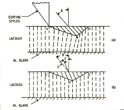
The CBS team expected to see a groove like pattern C in the figure left¹ in which the 15° tilt of the modulation would cause one part of the ramp to be foreshortened in relation to the other. Ben Bauer (head of the CBS team) called this pattern the Sarcophagus pattern.
But, they didn't.
Instead they saw no tilt and a regular rhombus pattern (shown at D) as if the record had been engraved with a cutting stylus with its pivot point lying in the plane of the record; something which they knew to be impossible.
Springback
After much head-scratching and some very clever experimental work, the CBS team determined the cause of this mystery which is due to the longitudinal elasticity of the lacquer. The action may be explained as follows (paraphrased directly from Bauer's article)¹.
Cutting stylus (A) in the figure (right), with a recording angle B is cutting the triangular velocity pattern we considered earlier. Initially the lacquer is in an unstressed condition. As the disc advances to the left, the tip of the cutter stylus moves along the slant lines, and cuts the shape a-b-c. Whilst the cutting action takes place, the shearing forces push the material forward, as shown by the slanted dash lines, the slant being proportional to the depth of cut, and greatest at b. When the cutter emerges at c, the stress is diminished and the material springs back taking on the form shown in (B). It is seen that the triangle a'-b'-c' has an equivalent vertical modulation slant C which is smaller than the recording angle B by the amount of a springback angle S.
Bauer's team determined experimentally that the cutter must be inclined by an additional 14° to end up with a 15° modulation angle. The adjustment of cutting angle was made conveniently by adding a 14° wedge to the cutter mount.
 A reliable 15° VMA (allowing for lacquer springback) was recognised as a real step forward in fidelity from early LPs. CBS' rivals RCA had also been working on the problem and the adoption of disc cutting allowing for lacquer springback underwrote the RCA Victor's Dynagroove recording system (the apogée of hi-fi at the time!).
All that was needed was for the record companies to inform and educate the cartridge manufacturers (with the help of the RIAA) so that cartridges were constructed with a VTA of 15° and the problem vertical tracking error would go away for ever.
But there was a problem: a VTA of 15° caused the cartridge body to ride very low in relation to the surface of the disc. Fifteen degrees’ tilt might have been fine for the cutter head which was rotating above a perfectly flat aluminium-backed lacquer: but it wasn't so fine for the phono cartridge riding so low that it risked fouling the surface of plastic, mass-produced, warped records.
In order that their products were useable with people's not-so-perfect record collections, the cartridge manufacturers struggled to adopt the 15° standard. To ensure adequate disc clearance, most cartridges - even to this day - measure between 22° and 35° VTA.
The CBS experimental work was performed on a Westrex record lathe and cutter-head. Bauer noted¹ that, at the time, European manufacturers had a much harder time compensating for lacquer springback because the form-factor of the European cutter-heads prevented alteration of the cutting angle.
Once European manufacturers had caught-up and did produce equipment which allowed for this extra tilt, mindful of the cartridge manufacturers and their grumbles of the insufficient 15° VTA, they (gradually) adopted the higher value of VMA of 20°.²
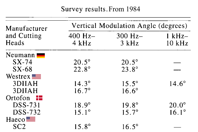
This led to a continental VMA divide which appears to have existed until the very end of vinyl era with cutter-heads of American design sticking to 15° VMA and European heads cutting with a VMA of 20°.³
The results of a survey of VMA in a range of lathes used various mastering facilities near New York published in 1984 is given in the table³.
Even though an international standard4 was eventually adopted by all lathe manufacturers in 1979, the cunning choice of a standard figure for VMA of 20° ±5° meant nobody had to change anything!
When a LP mastered on a modern European lathe is played back with a cartridge with a choice of low VTA (say 22°), the vertical tracking mismatch is negligible. However, a record mastered with an American cutter-head and played back with a cartridge of, say 35° (examples of which certainly exist today), the vertical tracking error will be 20°. The same cartridge would replay an early-sixties stereo disc with 35° vertical tracking error!
At what point should we become worried? What is the threshold at which the distortion due to vertical tracking error becomes audible?
Because lateral tracking error and vertical tracking error are so similar, we can use the rule of thumb we developed for distortion as a result of lateral tracking error (see Note. 7 on this page). It is the following:
If we take Olson's findings for the limits of just perceptible level of distortion on music reproduction5 (0.7% THD), it suggests that we ought not to tolerate more than 1½° of tracking error.
But it's been known for many years that certain liberties may be taken with the channel-difference signal compared with channel-sum information for the following reasons:
Because vertical tracking distortion "hides behind" information which is panned to stereo centre and is masked by information carried in the lateral modulation, it is greatly easier to hear if the vertical modulation may be auditioned in isolation.
 One study exists (from 2009) in which tracking distortion has been simulated using DSP so that it may be isolated from all the other distortions introduced in phonograph replay and thus rendered controllable enough to undertake listening tests for the perceptibility limits6.
The listening tests reported are not authoritative (they were not double blind and the panel was extremely small). Nonetheless the results are interesting. Its author (Richard Tollerton) reported that a vertical tracking error of just 2° was perceptible on synthetic test tones, but the figure rose to nearly 12° on music programme.
We decided to repeat the experiments for our own interest and informally agree with the limits discovered by Tollerton. To make these results more tangible, we have simulated distortion due to 12° of VMA-VTA mismatch as part of the following audio example .
The track is divided into four parts:
#1 - The original, digital recording
#2 - The original recording "infected" with distortion to to the equivalent of 12° vertical tracking-error
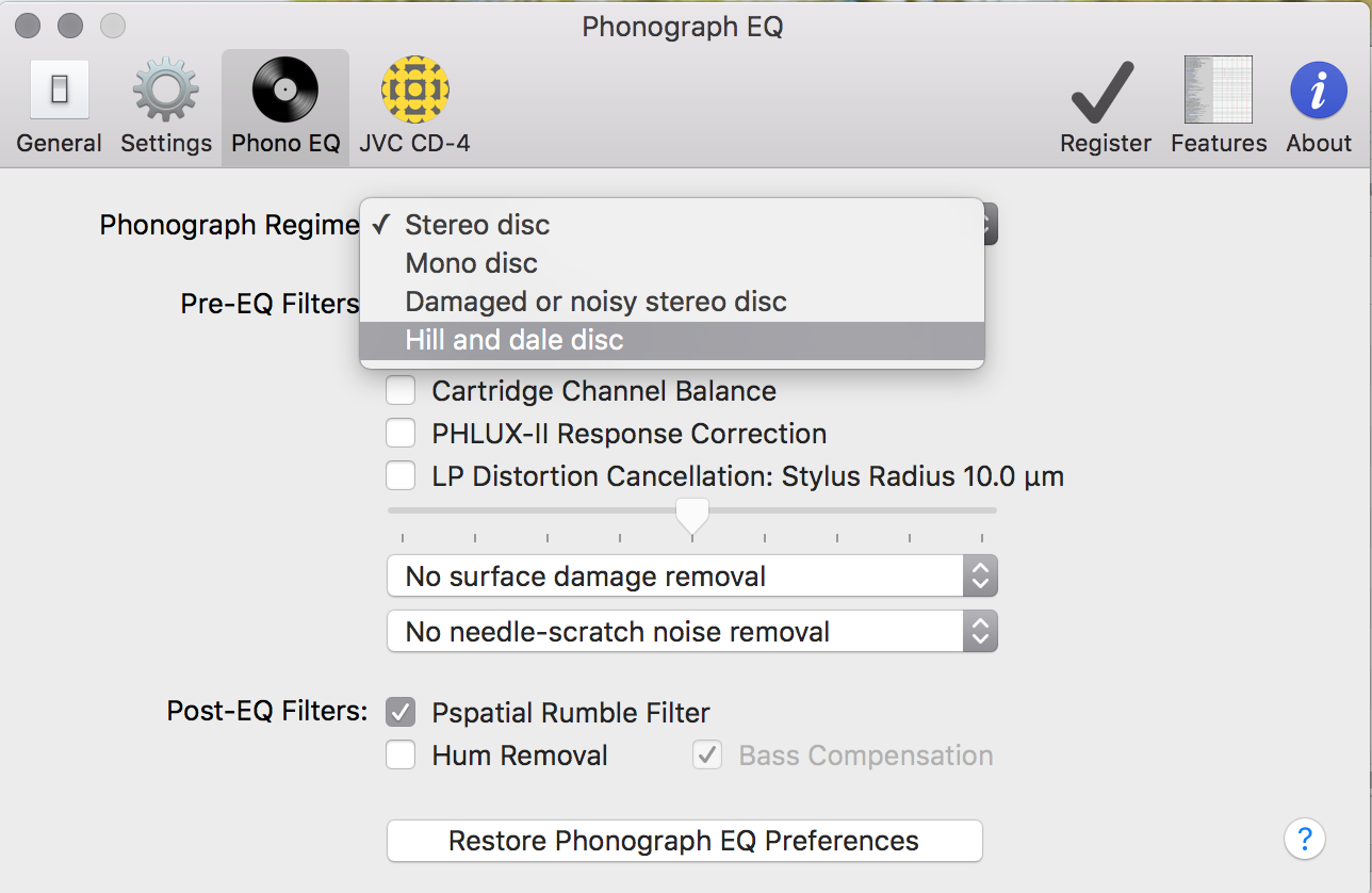
#3 - The original vertical-only signal (derived using Stereo Lab Hill and Dale processing)
#4 - The vertical-only signal after distortion has been added (derived using Stereo Lab Hill and Dale processing).
Judge for yourself: but we agree this degree of tracking-error to be just about audible on the main track. It is certainly audible on the isolated vertical-only signal (listen especially to the guitar in the intro'). Our own experiments and Tollerton's lead us to the conclusion that a sensible limit to vertical tracking error should be 10°.
An article published in Audio Magazine in 1981 has gone on to have influence on the high-end audio sector where its main conclusion has become something of a talisman.7
The authors (Jon Risch and Bruce Maier), discovered that, whilst vertical tracking error caused distortion at low frequencies in exactly the way that others had observed, another mechanism appeared to be at work when highly-elliptical, Shibta or line-contact styli were employed for replay.
In a somewhat sparsely argued article (see note to ref. 7), the authors rush to a conclusion that there is another optimum cartridge alignment angle. They called this angle the Stylus Rake Angle (SRA) and declared the optimum value to be 92°. The diagram illustrates how SRA is defined (but see note to ref. 8).
Risch and Maier present evidence for the advantage of orthogonal SRA over correct VTA on the basis of vertical tracking distortion: but only in a cartridge which is damaged or incorrectly manufactured (or modified8). And they hint (with reference to a torque mechanism) that marginal stylus tracking is to blame for the increase in distortion when a stylus is non-orthogonal with the groove modulation9.
Their advocacy for the predominant importance SRA over VTA is further driven by the casual observation that, "When SRA is correctly aligned the sound quality "locks-in" and the retrieval of minute details is enhanced", which suggests that, in their enthusiasm, they confused VTA for lowest distortion, with SRA for the best HF reproduction.
From our point of view, worrying about SRA is somewhat superfluous. If a cartridge has a stylus which, whether by accident or (bad) design is in a condition such that the intended VTA is not commensurate with an orthogonal SRA, there must be something wrong with it. In a correctly designed and manufactured cartridge, because of the fixed disposition of stylus, cantilever and pivot-point, correct VTA and SRA should never be incompatible.
Regarding the precise figure of 92° for SRA, see Appendix 2 which gives our own analysis of the importance of orthogonal SRA and the note to reference 8.
for correct VTA......
Some tonearms permit the adjustment of VTA by means of a height adjustment of the rear bearing gimbal with respect to the disc surface. Expensive models may even allow for micrometric adjustment. For reasons of rigidity, this adjustment is usually limited to about 1cm of travel which simple trigonometry reveals only influences the VTA by about ±1½ degrees.
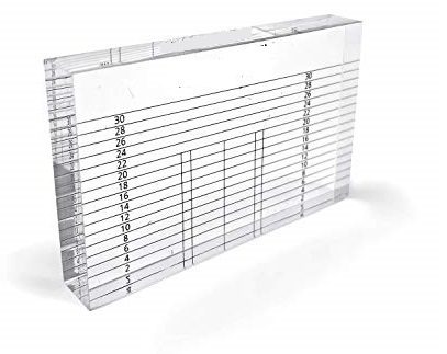 A reliable starting-point is to set tonearm height so that the tonearm, cartridge mounting platform (or headshell) are parallel with the record surface. Once a manufacturer has decided upon a given VTA (whatever value that may be), they will assume that the mounting face of the cartridge body (its top face) will be parallel with the record. Various aids may be employed to help with this; one of the simplest being an acrylic block with ruled, horizontal lines which may be rested on the disc whilst the height adjustment for parallelism is made.
Some find it preferable to set the correct tonearm height by looking for orthogonal (or 92°) alignment of the stylus/disc interface rather than to judge parallelism between tonearm and disc. However, the axis of stylus is often difficult to ascertain. Even Risch and Maier admit8 that SRA alignment, "is possible..., but it is difficult."
Given the rather elusive nature of the distortion due to vertical tracking error, it seems odd that that so much advice (especially "on-line") pertains to adjusting VTA "by ear". Guidance like this is commonplace,
"Set the pickup arm parallel to the turntable...then listen. If the arm is too high, there will be too much treble. If it is too low, not enough treble."
Instructions like this seem suspect. The limited range of adjustment and the fact that, in virtually all circumstances, VTA-VMA is positive mean that this method is unlikely to fine-tune for minimum vertical tracking error - or even to have much effect upon it.
If there is a perceptible "sweet spot" in the range of heights over which the tonearm gimbal mechanism may be modified, this almost certainly isn't due to adjusting VTA. Possibly, when a hyper-elliptical stylus is being used, the change is due to changing SRA (certainly Risch and Maier believed it to be7.8.) Appendix 2 gives our own analysis of the variation of frequency response with changing Stylus Rake Angle (SRA).
Note however that tuning for correct SRA should always produce maximum treble. The intermediate position recommended above results in mistuned SRA.
* Remember that European cutter-heads (especially the Neumann's) were widely used in the USA and vice-versa. So it isn't reliable to assume all records mastered in the USA are cut at 15° VMA: or that all records cut in Europe have a VMA of 20°.
Furthermore,
Determining the VTA of a cartridge is not straightforward. Most mortals are left simply trusting the manufacturer's specification. Sadly, quoted VTA figures are not always reliable.
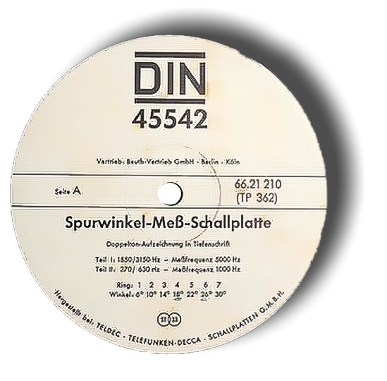
The ideal tool for measuring VTA is a test-disc with suitable test-signals cut at successively increasing angles of VMA; both below and above the 15-20° value. The VMA of the track which generates the lowest distortion on replay immediately identifies the VTA of the cartridge.
A couple of test LPs exist which follow this blueprint. One is the German DIN 45 542 test disc dating from 1969, on which are recorded a series of MF and HF intermodulation tests at VMAs of: 6° to 30° in increments of 4°. Another is RCA Victor Test and Technical Purpose Record, No. 12-5-78 which has an even more complete range of cutting-angles.
Regrettably, copies of either disc (in any condition) are very hard to find. And, in any case, interpreting the results from these records is somewhat specialised.
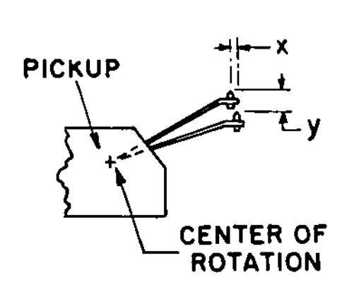
Essentially, the cartridge is measured by deflecting the cantilever from its unloaded (rest) position, through the position it takes up at the specified tracking force is applied and beyond. A calibrated force is required to do this.
At each weight point, the vertical and horizontal position of the stylus tip are measured and used as coördinates to make a plot of x a& y deflection on linear graph-paper. The VTA (θ) is derived from such a plot, its value being,
θ = arctan(δx ⁄ δy)
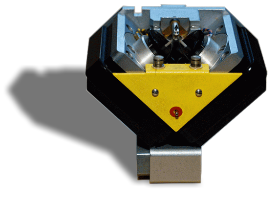
We use an old tonearm with calibrated tracking weight collar, a digital stylus tracking force gauge and a USB microscope to make these measurements. (Remember that it is only the ratio δx ⁄ δy which counts, so the dimensions chosen don't matter.)
If any form of elliptical stylus is not orthogonal with the groove, the situation is somewhat akin to incorrect head azimuth being set on a tape-machine. The resulting high-frequency loss being serious and appearing on the sum-signal and therefore being greatly more perceivable than vertical-tracking error.
In order for us to "get a handle" on the relative importance of SRA, we developed the following simple mathematical model for the effect of misalignment of a hyper-elliptical (Shibata) stylus with the groove modulation and the resulting high-frequency loss.
We modelled the greater vertical "footprint" of a Shibata/ line-contact stylus by assuming the the stylus touches the groove-wall at two, vertically separated points S distance apart.
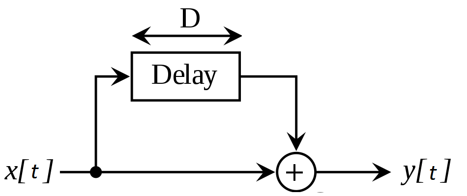
If the stylus is misaligned with the longitudinal modulation in the groove because it is canted-over at an angle of θ, this will result in the longitudinal distance between the points being defined by, sinθ × S. This distance has the dimensions of time as the record turns and the modulation is sensed by the two contact points. Thus, we can consider the output of such a stylus y(t) to be the combination of the input x(t) and the same signal delayed x(t - D). Like this,
y(t) = x(t) + x(t - D)
Taking the Fourier transform of this expression and deriving just the magnitude part, we get,
|H(ω)| = [(2 + 2cos(ωD)] ½ , which gives the (angular) frequency response of the model.
So, into this simple model, we can now substitute some dimensions such as we encounter with real styli and grooves. (See this page for information on the groove dimensions.)
Considering the innermost groove of an LP (where misalignment will cause the greatest high-frequency loss), the velocity of the stylus in the groove is ≈ 0.2m/s. And thus,
D = sinθ.S ÷ 0.2
Let's take S as 25µm. And let's take the SRA misalignment to be 10° Frankly both these figures are pessimistic since the footprint of a Shibata stylus isn't as "long" as this in reality and 10° error would represent a severe misalignment. But it's a place to start.
Substituting, we derive a delay of 22µS which, if we substitute back into our transfer-funtion |H(ω)| and plot, we get the following graph.
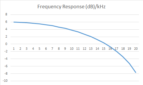
Which indicates an HF loss of 2dB at 10kHz and 14dB at 20kHz. Severe distortion indeed!
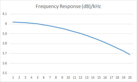
But, we knew these figures were pessimistic. So, if we consider a misalignment of 2° between stylus and modulation, the frequency response is reduced by only 0.3dB at 20kHz (and < 0.1dB at 10kHz) at the innermost groove, a degree which is certainly below perceptibility. The graph looks like this.
So, it seems that SRA is not especially critical. But neither should we be complacent about it. Severe misalignment can cause significant frequency-response errors. So, verifying the orthogonality of the stylus main axis with with the disc-surface is certainly worthwhile to ensure errors are not serious. The claimed sweet-spot" of 92° is probably something of an urban myth as a difference of 2° produces frequency response differences below the accepted audibility thresholds.
As to those who want to "tweak" for best VTA/SRA by ear, remember that the maximum angle of adjustment contrived by raising and lowering the tonearm gimbal over ±½ cm is 3°. Substituting the figures back into the expression for |H(ω)|, we can determine that this range of adjustment only offers about ±½dB of tonal adjustment at 20kHz at the outer groove of the disc. So this is a tricky adjustment to make with certainty.

Because Stereo Lab features a decoder for JVC's CD-4 quadraphonic discs in which the extra quadraphonic information is recorded in supersonic (30kHz) subcarriers, VTA/ SRA alignment is considered here for these discs as they represent a rather special case.
The simple model described here may appear to be something of a "blunt instrument" when considering CD-4 records because the simple notion that a Shibata or line-contact stylus touches the groove wall in only two places may seem too simple when considering wavelengths of modulation at supersonic frequencies.
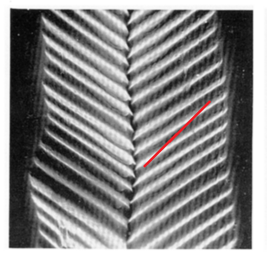
Yet, if one imagines a the CD-4 groove scanned by a rigid straight-edge of the stylus (as shown diagrammatically (right), it will indeed ride on the two "highest points". Thus, despite its limitations, the model produces some interesting predictions of the effect of a Shibata or line-contact stylus when it is not orthogonal with the groove when attempting to play CD-4 records.
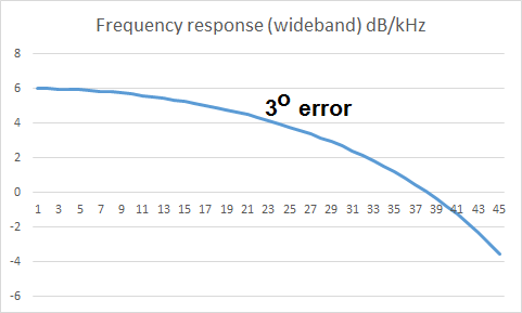
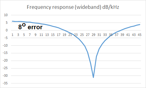
For example, look at the response errors in the subcarrier & sideband region (15kHz to 45kHz) due to 3° and 8° of misalignment. Eight degrees misalignment is enough to cause a null at the subcarrier frequency itself; a situation which matches the red-line in the illustration of the groove above. But the model predicts that, even only 3° misalignment, will create a fall of over 10dB over the subcarriers sideband range.
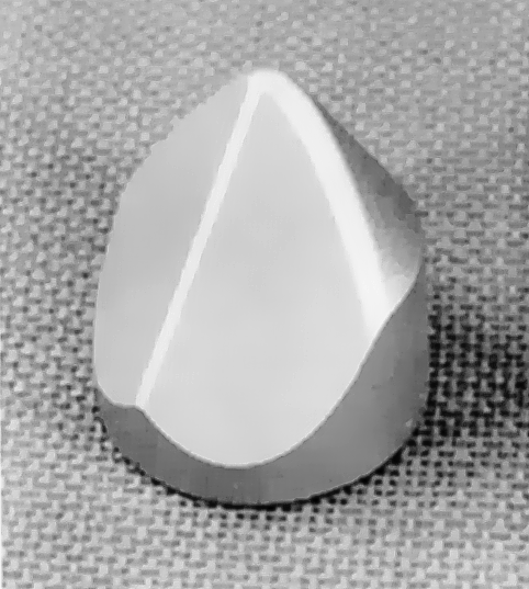
The alignment of SRA for CD-4 records represent one example where micrometric height adjustment of the tonearm bearing gimbal with respect to the disc surface is justified. This is especially so because the contact edge of the Shibata type stylus is not aligned with the major axis of the stylus chip as the model of the stylus shape (right) illustrates very clearly. This increases the difficulty of visual alignment for orthogonal SRA from difficult to almost impossible!
The tonearm height adjustment for CD-4 needle-drops should be made so that the subcarrier output is maximised when the recorded waveform is viewed in the DAW. Test recordings of some "dead-wax" (silent grooves) towards the centre of the record are best. If one exists, the inter-track grooves between the last two tracks on a side is very suitable because the subcarrier is always present even when the baseband modulation is silence.
1. Vertical Tracking Improvements in Stereo Recording Bauer, B.B. Audio Magazine February 1963
 2. The narrative is a simplification. European manufacturers certainly did initially adopt 15° VMA. Quite what date they changed to 20° VMA is unclear. In Britain at least, it was certainly after 1965 because the British Standard for LP discs still specifies 15° in the version published in that year (BS1928 :1965). And the version of the German Standard DIN 45-500 published in 1966 (a general standard for all types of audio equipment) still specifies replay VTA as 15°±5°.
The manual for the Neumann SX-74 cutter-head, published in Autumn 1973, reveals that Neumann were still struggling about which standard to adopt.
Care was taken with regard to the vertical tracking angle to assure, on the one hand, a 15° angle to meet the DIN 45542 standard and, on the other hand, the desire of the International Electrotechnical Commission (in IEC Publication 98) to standardize an angle of 20°±5°. For this reason the cutter was constructed to cut an 18° angle when correctly mounted. Lacquer springback is included in this calculation.
It seems to us that all discs prior to about 1972 (regardless of origin) should be considered to be cut with a VMA 15° or below.
3. Vertical Modulation Angles of Commercial Stereo Phonograph Records A. WOODARD. J. Audio Eng. Soc., Vol.32, No.3, 1984 March.
This article makes it obvious that the lack of standardisation in VMA and the discrepancies wth VTA existed until the very end of the heyday of stereo phonograph records. Given that Woodard's review of VMA and VTA was made two years after the introduction of the Compact Disc, it's certain that nothing has changed since.
4. Part 3: Specification for Record Playing Equipment and Cartridges IEC 581-3, 1979
5. Elements of Acoustical Engineering, Olson, H.F. D. Van Nostrand NY 1947
Olson's figure of 0.7% relates to just perceptible distortion due to a pentode tube. That is largely second-harmonic, so the analogy isn't unreasonable as tracking-error (in small amounts) is also predominantly second-harmonic too.
6. Digital simulation of phonograph tracking distortion, Tollerton, R. Paper given at AES 127th Convention New York, USA October 2009.
7. More than one Vertical Tracking Angle, Risch, J.M. and Maier, B.R., Audio March 1981
This article may have been brutally sub-edited to be suitable for a popular electronics magazine (rather than a journal) and, in so doing, the argument was considerably eroded. However, there does not seem to be any later work developing the work reported here.
8. Phonograph Playback It's better than you think! Maier B.R. et al. Popular Electronics November 1980
Confidence in Risch and Maier SRA recommendation of 92° is a shade undermined by conflicting advocacy in the two articles (Refs. 7 and 8). Reference 8 adivises, "The cutting stylus carves the record with a vertical contact profile "tipped" slightly forward (away from the tonearm) pivot by one or two degrees. Whereas, reference 7 says, "Proper hi-fi set-up should therefore concentrate on cartridge' adjustment that has the tip of the stylus pointed "back" toward the tonearm pivot,"
9. Insofar as it goes, Risch and Maier's argument is fair enough. We know that distortion increase with vertical tracking error rises quite slowly, whereas, distortion due to the stylus losing contact with the groove wall creates a "blast" of high-level distortion. So, in a cartidge where correct VTA and orthogonal SRA are incompatible, it might be justifiable to align on the basis of orthogonal SRA, rather than the more traditional VTA. But it is "over-egging the pudding" to claim that this demonstrates the a new counter-historical alignment angle.
10. Techniques for Measuring the Vertical Tracking Angle of Stereophonic Phonograph Pickups, Woodward J. G., J. Audio Eng. Soc., Vol. 13 No. 3 July 1965
Pspatial Audio Home page
For all support issues, go here.
For Pspatial Audio sales, email: sales@pspatialaudio.com