
| Support for cassette equalisation and noise reduction is due for release in Stereo Lab Version 4.2. |
Compact Cassettes ¢ the worldÆs dominant music medium
After the gramophone record, the Compact Cassette is arguably the second-most significant analogue storage-medium for music. Invented by Philips in 1962 as a tape for speech recording for dictation, the cassette gradually improved over the next twenty years. , By the mid-1980s, cassette sales surpassed LPs worldwide. The global reach of the format was remarkable. By the 1980s, cassettes were more affordable and durable than records, so in much of the developing world, cassettes became the dominant format ¢ sometimes well into the 21st century. Its legacy is even more significant. Home taping changed the music industryÆs business model forever, and the compact cassette launched todayÆs personal, mobile music culture.
Cassette mechanism
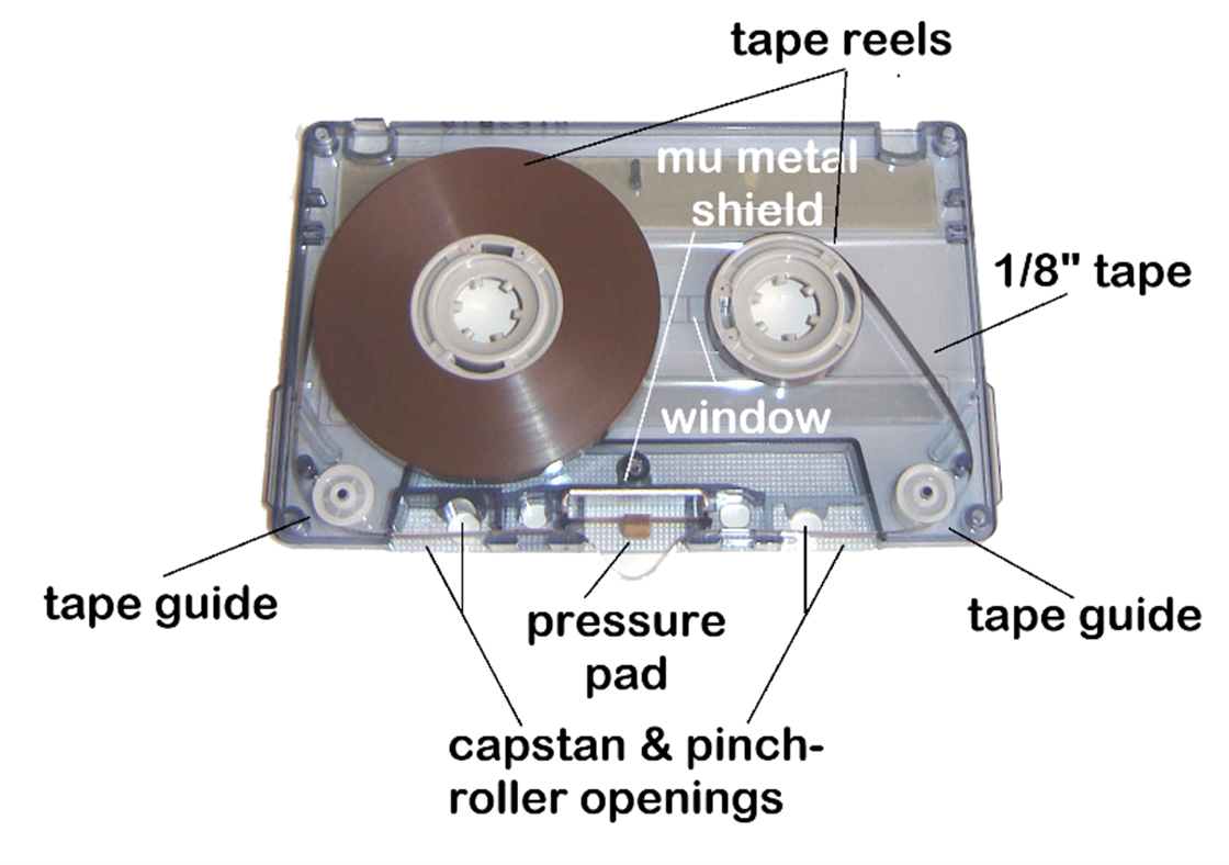
The compact cassette is a miscellany of synthetic polymer materials. In the device, magnetically coated polyester (PET) tape is passed between two small spools made of polyacetal (POM) to which the leader tape is firmly attached. These spools along with small, POM tape guide-rollers (running on nickel-plated steel, or stainless steel pins) are held inside a protective polystyrene shell (shown open, above). The flangeless, POM hubs are separated from the polystyrene housing by a PTFE liner (slip sheets) to avoid edge damage to the tape.
The cassette is snapped into position inside the player such that the capstan protrudes into the shell behind the tape, and the head-and-pinch-roller assembly are pushed into the void in the body of the shell at the front. Contrary to the majority of open-reel tape, in the compact cassette, the tape is wound oxide-out on the spools. The position of the cassette in the mechanism is aligned by two pins in the baseplate which engage with the radiused square holes adjacent to the two capstan openings.
The cassette mechanism ¢ with the cassette opened and the heads pushed into the play position ¢ reveals the full tape path. From left to right we can see the erase head, followed by the combined record/playback head and the capstan and pinch roller on the right.
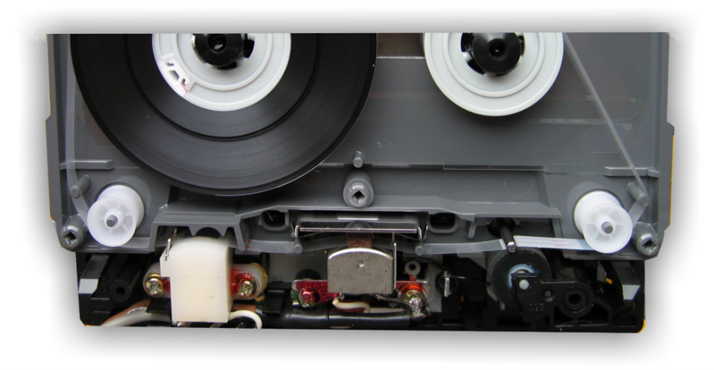
The mechanism is shown stopped. When set to play (or to record) the whole lower assembly is physically pushed into the cassette housing. The heads thereby contact the tape against the spring of the pressure pad, and the pinch roller pushes against the tape and capstan. The capstan and pinch roller mechanism is detailed in PhilipsÆ original cassette patent (right).
The use of pressure pads to hold the tape against the record or replay heads is considered unsatisfactory in open-reel tape recorders. It increases the drag on the tape and can accelerate head wear. However, in the case of cassettes, the original patent specification incorporated the pressure pad, and it is always present. The pressure pad is necessary because there is no control of the rear tension of tape prior to the heads as there is in all open-reel recorders. So, the tape wouldnÆt wrap properly around the head unless is pushed there by the pad. The pad assembly consist of a phosphor bronze, leaf spring with a felt cushion.
Philips only specified the size and pressure of the pad in their licence paperwork, (1 mm thick, density ≈ 0.25 g/cm│ and a pressure of 15 to 20 grans-force on the tape), but not the felt material. Charmingly, for a format built on an assortment of plastics, the material of the felt was often natural wool fibre in early and high-quality cassettes, right up to the 1980s, although polyester felt (Terylene) became common in the 1990s. The fibre nap of the pad must be very tight so that loose fibres do not work their way between the head and the tape to cause dropouts of the audio signal.
Note the shiny mu-metal shield behind the pressure pad. This is an integral part of the cassette tape design - its role is to shield the tape head from stray magnetic fields. The signals derived from the replay head from a narrow tape running at low speed with a tiny gap are very small indeed (≈ 0.3mV RMS for a 1kHz tone with recorded flux -12dB from tape saturation), and ōhumö is an ever-present menace ¢ especially given the enormous level of amplification tape equalisation requires at low frequencies. As cassette decks improved (with better head shielding, lower field leakage, and lower impedance heads), the shielding role became less critical, and manufacturers switched to using plain steel or other cheaper alloys for the backing plate. By the 1980s, only high-quality blanks retained proper mu-metal shields.
Track arrangement
In a stereo audio cassette, four (0.6mm) audio tracks are recorded across the width of the tape: two (stereo left and right) in one direction, and two in the other. This means that the cassette is ōflippableö like a record, and plays both sides, hence the symmetrical design of the cassette shell.

By means of a slow tape speed of 17/8 inches/second (4.76 cm/s) and very thin tape, a typical cassette runs for 30, 45, or 60 minutes of audio per side (called C60, C90, and C120 formats respectively). Cassette tape thicknesses are lower than the tapes for professional machines: 18Ąm for C60 cassettes, 12Ąm for C90 tapes, and 9Ąm for C120 cassettes. The C60 cassette contained 90 metres (300 feet) of tape.
 The performance of the original analogue cassette was very poor, and way below the performance of contemporary gramophone-records. However, its performance was improved by Dolby B, and by the very considerable improvement and innovations in tapes themselves, as we shall see.
Cassette players were among the most widely produced consumer electronic audio devices in the late 20th century given their presence in portable radios, car stereos, ōboom boxesö, portable players, and different home setups. Combined with mechanical refinements (better shells, slip sheets, and precision hubs), various innovations meant that by the early 1980s, the compact cassette rivalled LPs in fidelity for many non-critical users. And, thanks to its portability and recordability, the cassette briefly became the worldÆs dominant music format.
Cassette tape tabs
Cassette shell design incorporated tabs in the top rear edge of the cassette housing, one above each reel. These were to prevent accidental erasure or to prevent a new recording to be made over a previous precious recording. They are sometimes called erasure prevention or write-protect tabs.
When the tab is intact (left), a sensor pin on the record deck is depressed when the cassette is inserted, and the machine allows recording. If the tab is snapped off, the hole is exposed, the recorderÆs pin penetrates the hole and disables the record control or circuit. (If you subsequently want to record again, you can ōfixö it by covering the hole with a bit of adhesive tape.)
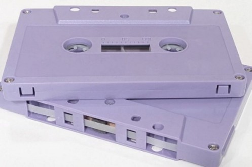
As cassette technology advanced and different tape formulations were introduced, it was considered desirable that the machine knew automatically what type of tape was to be recorded (each required different bias levels) and played back (each required different equalisation) and the tab system was extended to indicate to the machine what bias and EQ was required.

The photograph right illustrates the standardised notches for automatic tape selection: There are two notches for Type II (next to the write-protect tabs), and four for Type IV. The Type I cassette (and Type III) tape is top, Type II is in the middle, and Type IV at the bottom. The position of these notches was standardised in IEC 60094 (originally designated IEC 94).
Tape formulations
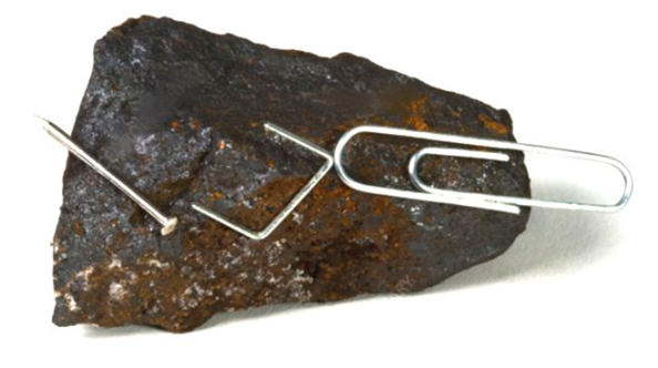 Gamma ferric oxide (γ-Fe2O3) coatings remained the baseline magnetic coating of all magnetic tapes from the 1940s to the 1970s. Prior to 1940, tape coatings (all open reel at that stage, of course) were based on Fe3O4 ¢ the naturally occurring iron oxide named magnetite, the most magnetic of all the naturally occurring minerals. Naturally magnetised pieces of magnetite, called lodestone (illustrated), are how ancient peoples first discovered magnetism. It was an obvious choice as the basis for a magnetic layer to be applied to tape.
The switch to gamma ferric oxide (γ-Fe2O3, sometimes called maghemite) was made because maghemite can be produced in considerably finer particles than ground magnetite. The gamma in γ-Fe2O3 refers to a specific crystal structure of iron(III) oxide Ś one that differs from the more common α-Fe2O3 (hematite) which is only very weakly magnetic. The γ-Fe2O3 crystal structure is similar to Fe3O4 (magnetite), and the production of tape dopes involve, specially prepared magnetite being oxidised to gamma-ferric oxide.
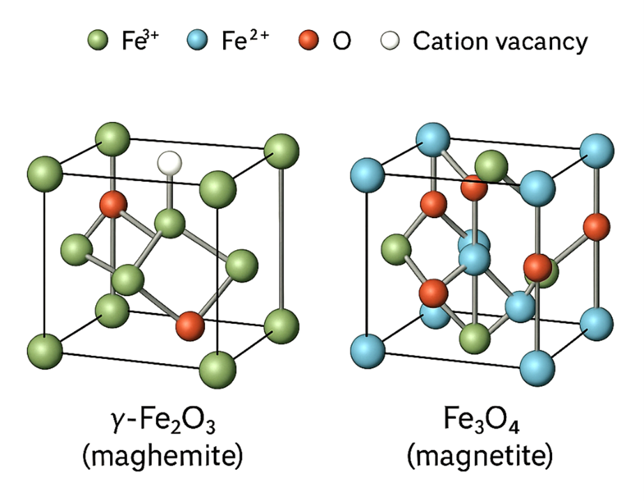
You may be puzzled. If gamma ferric oxide has a similar crystal structure to magnetite, how is it possible to produce smaller particles? The reason is that maghemite (γ-Fe2O3) is easier to grind than magnetite (Fe3O4) because its crystal structure is full of tiny imperfections. When magnetite oxidises into maghemite, some of its iron ions are lost, leaving empty sites ¢ or vacancies ¢ within the lattice. These missing atoms weaken the network of iron¢oxygen bonds and introduce strain that makes the crystal more brittle. Magnetite, by contrast, has a tightly ordered structure. In short, maghemite grains are more likely to fracture when ground or milled. Stick and ball models of the unit cells of magnetite and maghemite are illustrated.
Typical oxidation conditions consist of ōslow cookingö the magnetite at a temperature of 200¢300░C in a rotary kiln for many hours in an atmosphere of moist air or a carefully mixed flow of air and inert gas, like N2. Nitrogen acts as a diluent and atmosphere moderator, controlling how much oxygen the magnetite actually ōsees,ö and therefore how fast the oxidation proceeds. It also provides a safety margin Ś it reduces the risk of local overheating or combustion of fine powders (which are pyrophoric when partially oxidised). The 200¢300 ░C range used for converting Fe3O4 to γ-Fe2O3 is chosen because it is deliberately below the temperatures that causes the phase transformation to α-Fe2O3 (hematite). That happens above ≈ 350░C.The dimensions of the resulting iron oxide particles are in the region of 0.1 - 0.75Ąm with length-to-diameter ratios from 3:1 to 10:1.
In the professional audio world (studios, broadcasting, and mastering), gamma ferric oxide tapes for open-reel machines were overwhelmingly dominant, right up until the advent of digital recording technology. But the extreme limitations of the cassette tape medium drove substantial improvements in tape formulations for this market.
Why cassettes drove innovation
Magnetic tapeÆs intrinsic noise arises because of the essentially granular, or particulate, nature of the magnetic material in the tape coating. The phenomenon is essentially a statistical problem, related to the distribution of the individual signal elements. This is best appreciated by comparing a fast tape-speed, reel-to-reel recording with a recording on a standard cassette (assuming the same tape formulation). A professional recorder recording a 2.5mm track on a machine running at 15ips (38cm/s) encounters thirty times more grains (and thereby magnetic domains) per second than the cassette player, with a track width of 0.6mm running at 4.76cm/s.
Noise scales inversely with the square root of the number of domains interacting with the head at any instant, so the cassette tape is six (√33.6) times, or 15dB, more noisy than the same tape on the open-reel machine. Now, 15dB is a very severe loss of dynamic range ¢ remember professional tape machines were limited (without Dolby A) to a dynamic range of about 60dB at this time. Clearly, the compact cassette was destined to remain a very limited quality medium without innovation on the tape front.
On the other hand, the format was becoming increasingly popular with consumers. In the heyday of the cassette, the market for cassette tape was truly enormous. A Washington Post article states the worldwide market for blank cassette tapes was over one billion units/year in 1977. The economic incentive to develop new tape formulations to improve the performance of the format was thereby enormously significant.
It is to the chemists, as much as to the precision mechanical engineers, that we owe the development of the compact cassette medium from a format for office dictation to the hi-fi medium it became by the 1980s.


 The Nakamichi Dragon cassette deck is justifiably venerated for many reasons, but most of all for its automatic azimuth correction mechanism, which Nakamichi named NAAC (Nakamichi Auto Azimuth Correction).