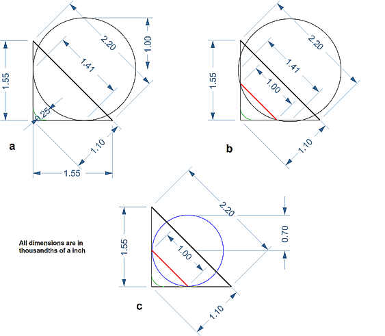
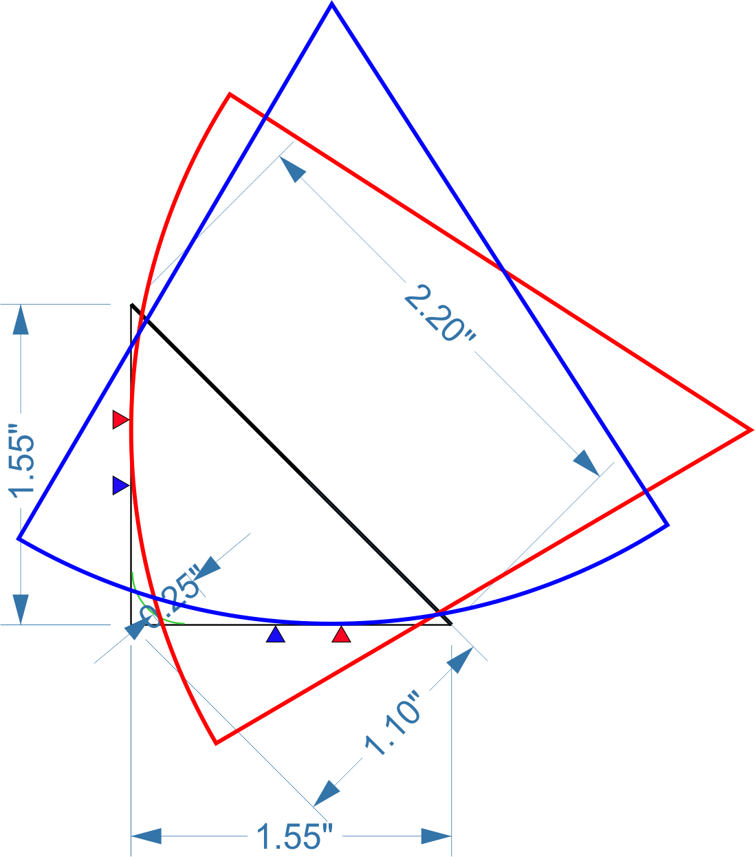
 A original, standard microgroove diamond stylus of conical (spherical) form has a radius of 25μm (0.001"). The groove width at the point of engagement with the stylus (half-way up the wall of the groove) is 36μm (0.0014") as illustrated at (a).

The groove is drawn to scale in the illustrations below. (Note that the illustrations are tilted over by 45° to make the geometry easier to understand.)
The depth of the groove is nominally 28μm (0.0011"). The bottom of the groove is not, in fact, a sharp corner but has a radius of 6μm or 0.25 thou' (0.00025").
A original, standard microgroove diamond stylus of conical (spherical) form has a radius of 25μm (0.001"). The groove width at the point of engagement with the stylus (half-way up the wall of the groove) is 36μm (0.0014") as illustrated at (a).
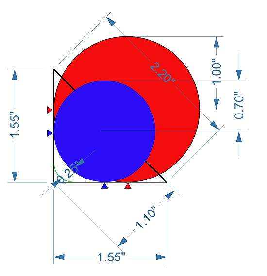
The groove of a mono record possesses modulation which is entirely lateral (side to side). When a 0.001" stylus rides in such a groove, it rides at the same height at all times; comfortably half-way down the groove.
Stereo gramophone records are different from their mono forebears in that the groove is modulated vertically as well. The RIAA standards for the dimensions of gramophone records defines the depth of this modulation in terms of the minimum allowable-width at the top-edge of the groove. This specified to be 25μm (0.001") as this dimension is illustrated by the red line at (b).
As the illustration at (b) clearly shows, a stylus with a radius of 25μm (0.001") runs a very good chance of disengaging when the groove is that shallow. For that reason, monophonic styli are not recommended for stereo records. Stereo styli adopt a radius of 18μm (0.0007") so as to stand a better chance of staying in a vertically modulated groove as illustrated at (c). But this does, of course, mean that a stereo stylus is rides "lower" in the groove than the mono stylus as illustrated below. (The coloured arrows indicate the point of contact in each case.)
It's worth remembering that the bottom radius of the groove on monophonic microgroove records was not specified, which is why the converse is also true: that a stereo stylus is often unsuitable for listening to mono records.
The first sounding turn of the groove of a 12" LP record has a radius of 146mm, and the last a 56mm diameter. The length of the first turn is thus 2 x π x 0.146m = 0.917 metres. And the last, 0.352 metres.
Given that a record turns at 33⅓ RPM, which equates to 0.556 turns per second, the velocity of the stylus within the groove is 0.509m/s (20 inches per second) on the outermost turn and 0.196m/s (8 inches per second) on the innermost. A 10kHz sinewave inscribed in the groove wall has thus a wavelength of (0. 509/10000) = 51μm on the outermost turn of the groove, and a wavelength on the innermost turn of 20μm.
Once again, these dimensions of the basic stylus within a groove are illustrated to scale in in the figures below. It's easy to see how a stylus of standard dimensions may negotiate 10kHz on an outer groove (d), but not on an inner groove (e).
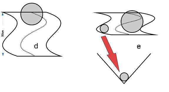
One apparently obvious solution to this is to reduce the radius of the stylus. But, as illustrated at (e), a stylus with a dimension much smaller than about 25μm will ride too low and may even "bottom" in the groove where dust and dirt collect and generate unneccesary noise on playback.
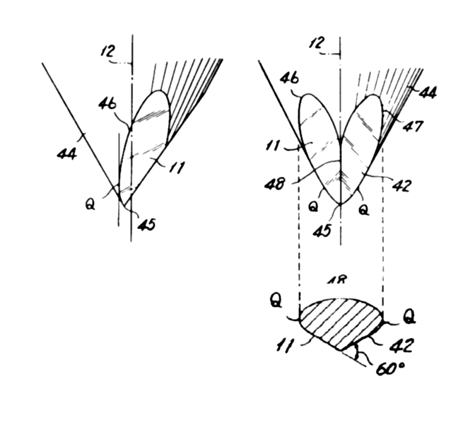
The commercial solution to this need to trace high frequency details without bottoming the stylus in the groove came with the elliptical stylus which was invented by Grado in 1964 (although Edison invented a very similar idea in the button stylus forty years earlier). The elliptical stylus is illustrated below which is from Grado's patent.
 RAB cleaned.png)
The elliptical stylus has a major radius (R) of 18μm (0.0007") such that the stylus rides at the correct height in the groove, but has a minor axis (r - usually of about 10μm or less) which improves tracing. The combined dual-radius stylus being referred to, for example, as R/r = 18μm/10μm.
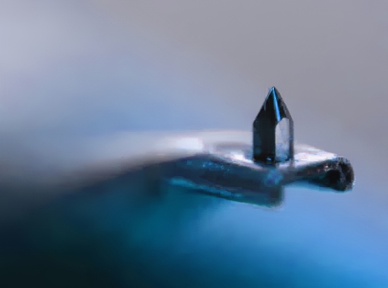
More exotic styli are formed by making further cuts to the diamond stylus so that the defining radius is even smaller than with a conventional elliptical stylus. The first of these styli was invented in 1973 to reproduce the high-frequency carrier signal for the extra two channels in CD-4 quadraphonic records and is known as a Shibata type after its inventor. It is illustrated below.
Ten years after Shibata, Van den Hull in Holland invented a derivative in which both the front and the rear face of the diamond are cut so that the profile has an even sharper edge. This technique too has been widely copied and is now referred to by a number of names including Micro-line or Micro-ridge. These styli have minor axes of 4μm or less, the smallest being around 2.5μm (0.0001"). This is a very fine edge indeed and a considerable engineering achievement, for this dimension is only about 5 times the wavelength of light.
In addition to the smaller minor radius, the Shibata stylus and its derivatives have sides which are less rounded than a conventional elliptical. In fact, the major radii of these types of stylus are often actually described as >>25μm (0.001") which sounds counter-intuitive. How does a stylus with a major specified radius of >25μm stay in a conventional groove? The explanation lies in that the centre of the two major radii are not coincident as the diagram below illustrates. (Here, both major radii are 75μm or 0.003".)
This is how line-contact styli are referred to as having an apparently impossible radius-ratio of , for example, R/r = 75μm/2.5μm (0.003"/0.0001").
This greater major-radius helps the stylus makes contact with the groove wall over a greater area. The conventional spherical (conical) type theoretically only touches the groove at two points. The difference is well illustrated in the image below. The conical stylus is on the left and the Shibata on the right.
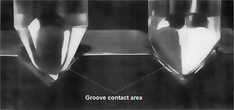
The increased footprint of the Shibata type stylus is said to bring with it a number of benefits. Because the stylus mass acts over a larger area, wear to the record is reduced and, more importantly, the stylus rides on parts of the groove wall where previous spherical styli have not worn away or damaged the information. Thus, even a damaged record, may become playable again with a hyper-elliptical stylus type. This aspect of the Shibata type stylus was well researched for the performance of CD-4 records. The case for this type of stylus reducing wear when used with standard stereo records is less secure.
Furthermore, because the high-frequency resonance of any cartridge is formed by the effective mass of the stylus tip bouncing on the compliance of the plastic record material, a larger footprint makes for a stiffer spring and a higher resonance frequency. These benefits are well researched and documented and have ensured that the Shibata stylus and its derivatives have gone on to remain the profile adopted in the highest quality cartridges despite the failure of LP-based quadraphonic sound.
Line-contact styli do however have the characteristic that the intersection of the two major radii is close to the bottom of the groove: both the diagram and photograph above illustrate this clearly. Sometimes these styli are truncated to reduce this dimension but these styli types are generally unforgiving of dirty records!
If we imagine a sinewave modulated track we can say that the dispacement of the stulus x(t) may be represented by,
x(t) = a . sin (ωt) ............ [eq.1]
where a is a is the amplitude scaling. Now, the voltage generated from a magnetic cartridge E(t) is proportional to the velocity of the modulating signal, or
E(t) = k. v(t) = k . dx(t)/dt ........... [eq.2]
The letter k being a constant which defines the sensitivity of the cartridge. If we let x(t) be the modulation as defined above, we can calculate the velocity (by differentiating), which is,
v(t) = (ω) . a . cos (ωt) ............ [eq.3]
which reveals that the output from a magnetic cartridge rises with (ω) or frequency.
The acceleration of the stylus is given by differentiating this last expression again, thus,
a(t) = -(ω)2 . a . sin (ωt) ............. [eq.4]
The maximum permisable modulation of a record groove utilises all the land between the grooves and thereby has the dimension of about 76μm peak to peak (or 38μm peak). Let's imagine a sinewave modulated groove at 400Hz and substitute these figures in equation [3] and [4].
The peak velocity is a relatively unsurprising 0.1m/s. But the peak acceleration has an (ω)2 term and is,
a(t) = -(6238)2 . 38μm . 1
= 240m/s/s, which is about 24 times the acceleration due to gravity. A surprising figure! And at higher frequencies, the accelerations involved become quite amazing.
Groove deformation under the weight of the stylus
Similarly surprising, although the tracking force of a modern cartridge is only perhaps a couple of grams, because the area of contact with the record is so small, the pressure at the contact point rises to extraordinary levels.
From work done by Hertz (when he wasn't discovering radio waves), we know that the pressure exerted by a hard, spherical indenter on a flat surface increases with the square of the reciprocal of indenter radius. So the pressure at the surface of the vinyl from a 0.7 thou' (18μm) stylus with a 2 gram tracking weight is equivalent to 37 grams weight exerted by a 3 thou' steel gramophone needle. That's over an ounce and nearly equivalent to the tracking weight of an acoustic gramophone soundbox.
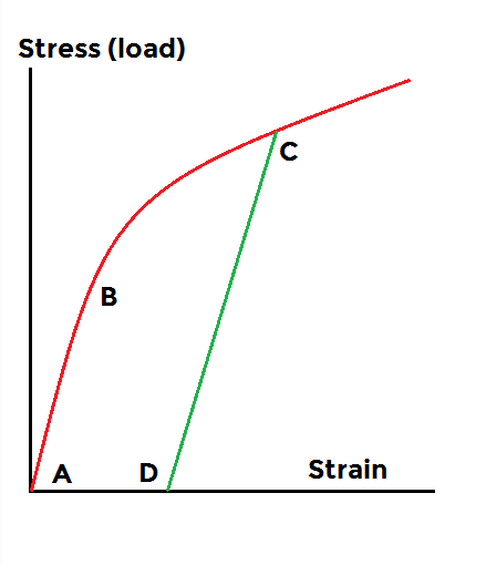 Before we look at what happens to vinyl at these very high pressures, let's briefly revisit the behaviour of a material under stress. When a material is loaded and the strain1 is plotted against the stress of the load, a curve like the one shown (right) is obtained, the exact shape depending on the particular material.
The straight part of the curve from the origin to point B is the elastic region where the material obeys Hooke's Law and extension or strain is proportional to load. When the material is unloaded it returns to its original size and shape unchanged. The slope of this portion of the curve gives Young's modulus.
At point B, yielding occurs as the material is taken beyond its elastic limit. This limit is known as the yield-point. Increasingly the load will from now on permanently deform the material until it eventually breaks or ruptures. This region prior to rupture is known as the region of plastic deformation. If the load is increased to point C and the load removed, the material will still spring back (and with the same Young's modulus) but the shape of the material will now be permanently deformed (curve C - D). Point C represents the new increased yield stress of the now work-hardened material. If it is re-loaded with the same load corresponding to point C, no further plastic deformation takes place.
Scale model experiments with the material used to make LP records and small (but not microscopic) indenters has verified2 that the load presented by even the lightest cartridge extends the strain of the record plastic several times beyond its elastic limit and into the plastic deformation region so that, even the first-playing of a record will alter its dimensions causing a furrow to be inscribed on the groove wall where the stylus has passed. The good news is that, once this has happened, the now work-hardened plasic will show no further deformation at the same tracking weight.
Barlow3 puts it bluntly,
During the initial playing of a record, the stylus will plastically deform the groove until it has sufficient area and has been sufficiently work hardened to support the stylus without further deformation. ...... The damage is done on the first playing and there is no means of telling what a virgin record would sound like.
Repeatedly stressing a material below its fracture stress may lead to eventual fracture. This is known as fatigue. If the repeated stress is well beyond the yield-point, only relatively few repetitions may be needed to fatigue the material, its failure being indicated by cracking or flaking, giving a pitted surface. Electron microscope images of well-played records may indicate that some kind of fatigue mechanism is involved in the increasing surface noise when a record is often played.
 Normally the diamond of the stylus is bonded to a metal (usually aluminium) shank and this is glued to the end of the cantilever which is flattened at one end to accept the adhesive and stylus assembly. In top-of-the-range cartridges, a longer diamond stylus may be bonded directly to the cantilever without the intervening metal shank. This type of stylus is referred to as a nude-shank type and is generally considered better because of a claimed reduction in the mass of the stylus assembly which ensures better tracking.
This claim seems odd given that the density of diamond is some 30% higher than aluminium. In fact the drop in mass is typically accomplished by diminishing the shank dimension and having the cantilever ride very close to the disc surface. This makes nude-shank styli sensitive to clogging with dust and lint. One tiny thread of lint trapped around the tip can gather small particles and lint like a broom and in a very short time a ball of lint and dust surrounds the tip between the record and the cantilever and this lifts the stylus upward and away from the groove walls.
Nude-shank styli demand that the user keeps her records scrupulously clean.
Nude-shank styli may be further divided into rectangular (or square shank) and round-shank styli. Rectangular nude styli cost even more to manufacture than round shank nude styli, but mounting them in laser-cut square holes in the cantilever locks them precisely in correct alignment.
All the above concerns 33⅓ LP records (and 45's mutatis mutandis). For information on groove sizes and styli for 78 records go to the Help-page about "78s".
1. The same principle applies (roughly) in extension and compression; although the performance - for any given material - may be quite different. In looking at records, we are considering the vinyl chloride-acetate copolymer in compression.
2. Barlow, D. Groove deformation in gramophone records, Wireless World, April 1964
3. Comments on the paper On stylus wear and surface noise in phonograph playback systems JAES July 1956
Home page
For all support issues, go here.
For Pspatial Audio sales, email: sales@pspatialaudio.com