Stereo Lab - Phono cartridge balance and azimuth

Cartridge Balance & Azimuth
 Stylus azimuth is a curious term and largely inaccurate¹. It refers to the perpendicularity of the stylus to the recorded surface when looking at the cartridge body from the front. It is most evidently betrayed by the clockwise or anti-clockwise tilt of the cartridge body with respect to the turntable platter.
So why not just aim to mount the cartridge body so that it isn't slanting with respect to the record surface? The reason is that, despite being a good place to start, azimuth is not necessarily correct when the sides of the cartridge body are perpendicular to the record surface because the cantilever may not be mounted exactly coincident with the axis of the body. And the stylus may not be attached to the cantilever exactly on the same axis either.
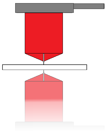
A simple way to check for azimuth is to stand the stylus on a small mirror (ideally selected to be about the same thickness of a record) and check that the stylus axis - and its reflection - are not bent with respect to one another. If the stylus is impossible to see (it often is), you can at least make a similar judgement concerning the cantilever and its reflection.²
Fozgometer
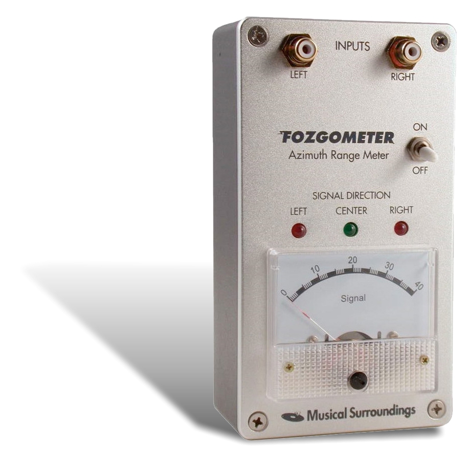
Because of the difficulty of making an accurate optical judgements, various electronic means have been developed to aid with the adjustment of azimuth. Celebrated amongst these gadgets is the Fosgate Fozgometer from Musical Surroundings. This unit, combined with recorded tones from a test record, may be used to determine correct azimuth by means of measuring and matching crosstalk between the channels as the azimuth angle is changed between test-runs.
Automatic compensation
Stereo Lab uses a technique similar to the Fozgometer to measure and minimise crosstalk between the channels of the cartridge and will automatically correct for azimuth errors. The process is selected by checking the Cartridge Balance and Azimuth check-box in the Phono Preferences tab. The software uses statistical information from the needle-drops, so no special test disc is necessary - and no fiddly adjustments are required. The converted audio file is corrected automatically to compensate for incorrect azimuth.
Appendix - Equivalence of Imbalance and Azimuth
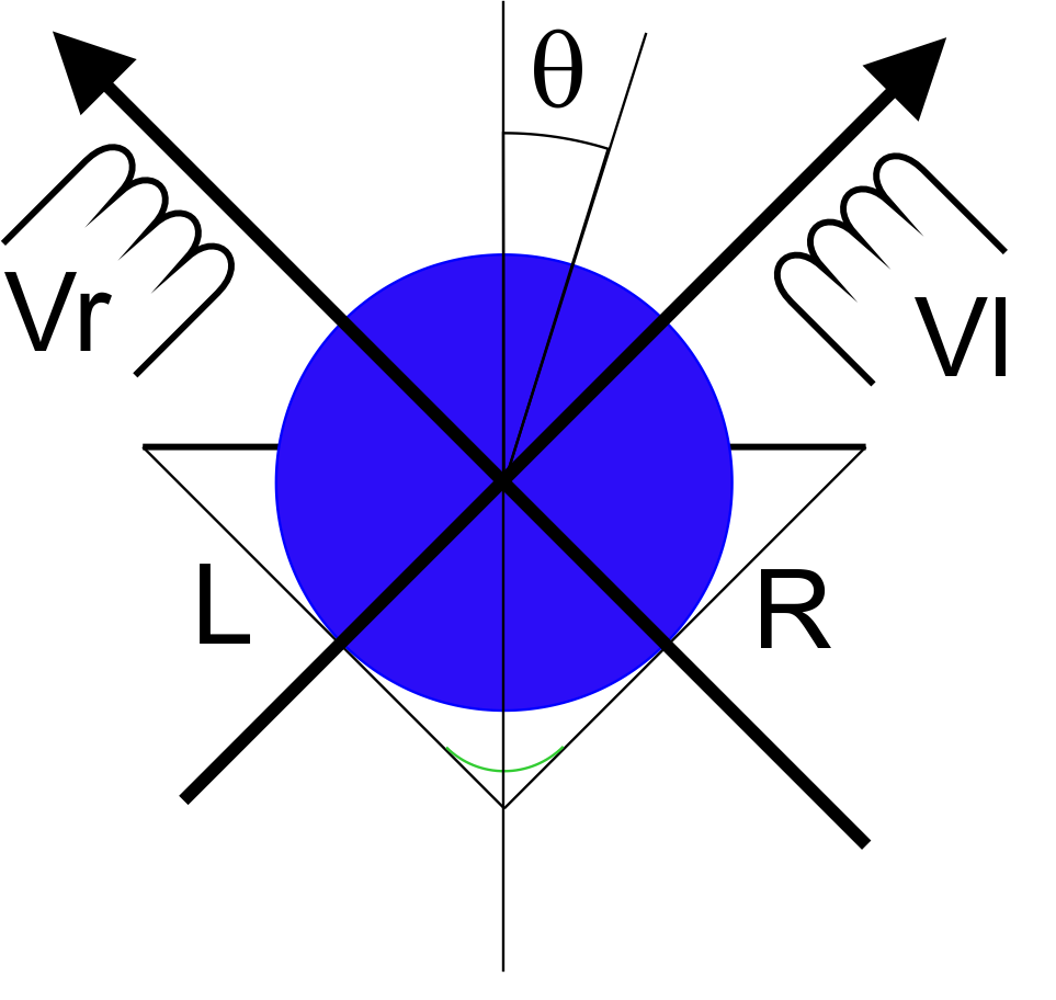 In the diagram, we are looking at a scale-drawing of the stylus radius (the blue circle) engaged in the triangular trench of the stereo groove. The mechanism by which the movement of the stylus translates to movement of magnets near two coils we'll ignore for the moment. We'll just assume a perfect device so that, however the stylus moves, it will move magnets which will induce exactly proportional voltages (Vr and Vl) in the orthogonal coils.
Imagine for a moment that only the right-hand-side of the groove is modulated and that the stylus is therefore moving solely along the right-axis. It moves either side of the L axis, but not along it and thus no voltage (Vl) will be induced.
Now imagine that the whole arrangement (except the groove) is rotated by an angle θ. Now movement of the stylus due solely to modulation of the right groove wall will result in movement along the R and L axes. Granted the movement along the R axis will be much greater than the movement along the L axis, but some of the energy will have bled from the right channel to the left channel. This is the origin of crosstalk due to the misalignment of the azimuth (by angle θ). We can even predict the effect to know that instead of the output being entirely in the right channel, the new outputs will be modfied such that, if we take the original modulation voltage (prior to rotation) to be Vr, the new outputs will be,
Vr' = Vr × cosθ and,
Vl' = Vr × sinθ
This signal modification is exactly equivalent to the change obtained by turning a (properly designed) balance control on a preamplifier, or what happens when a stereo microphone array³ is rotated by angle θ. In other words, it will shift the stereo image in the direction of the crosstalk. It is this equivalence of balance and azimuth which underwrites the use of electronic ratio detection equipment (like the Fozgometer) to determine correct azimuth.
However, there is a catch. Nothing in this world is perfect and phono cartridges remain one of the most fragile links in an analogue reproduction chain.
Let us assume that, due to misalignment in manufacturing of the magnets and coils, that the efficiency of the generator which produces Vr differs from the efficiency of the generator which produces Vl by 10%.4
This imbalance is equivalent to an azimuth rotation (θ) of,
sinθ ÷ cosθ = 0.1
a condition which is satisfied when θ ≈ 6°.
An uneasty trade....
The equivalence of imbalance and azimuth described above underpins the perhaps uncomfortable fact that azimuth alignment on the basis of ratiometric detection can result in an non-perpendicular azimuth being adjusted in order to restore an imbalance elsewhere in the transducer.
Now this is fine as long as the imbalance is fairly small and the stylus is a conical type. (The mathematical equivalence of azimuth-induced imbalance and intrinsic imbalance in the electrodynamic cartridge is only truly valid for spherical styli.) There is room of conjecture that physically aligning other stylus types ratiometrically may be unwise.
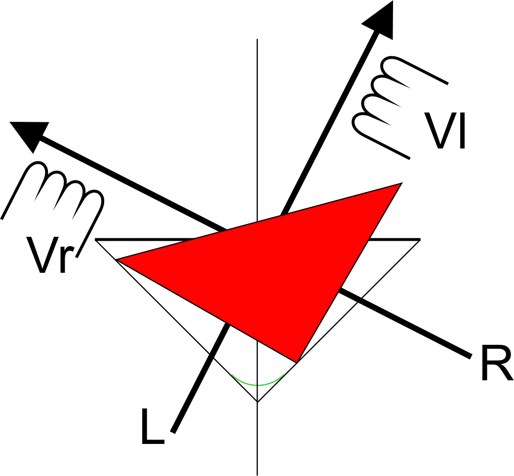
The diagram right illustrates azimuth misalignment of a Shibata/line-contact stylus. Not only is the mathematics described above not valid for a stylus of this profile, but a non-perpendicular azimuth possibly has much more serious consequences (on tracking and groove-wear for example) when considering these types.
The Balance & Azimuth compensation in Stereo Lab corrects for misaligned azimuth as well as imbalance in the cartridge (and indeed, the record level settings selected when making the needle-drop) without the need physically to slant the cartridge.
References and Notes
1. Azimuth refers to an angle around the equator of a spherical coördinate system. Its use in this context probably comes from a superficial connection with head-azimuth in a tape recorder where the term has some meaning, as it would have if the term was applied to Stylus Rake Angle which is analogous to head-azimuth. As it is, a simple term like stylus slant would be much more appropriate.
2. Many tonearms and/or headshells do not provide a mechanism to adjust azimuth in which case adjustments must be made by shimming the cartridge base (with shims or washers).
3. In the case of the cosine or figure-of-eight array.
4. This is not uncommon at all, even the best cartridges, the balance is rarely better than ± 1dB which is a 26% difference.
Links
Home page
For all support issues, go here.
For Pspatial Audio sales, email: sales@pspatialaudio.com
© Pspatial Audio 2015 - 2020. All rights reserved.  Apple Certified Developer. Stereo Lab, Aria 51, Aria 20, Head Space, Groove Sleuth, iLOOP and FRANCINSTIEN T-Sym are trademarks of Pspatial Audio. FRANCINSTIEN and Bride of FRANCINSTIEN (BoF) are trademarks of Phaedrus Audio. Macintosh and the Mac logo are trademarks of Apple Computer, Inc.