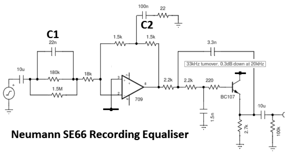
Simplified schematic of the Neumann SE66 recording equaliser in the VG66 disc recording electronics system

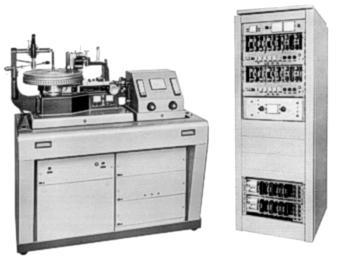
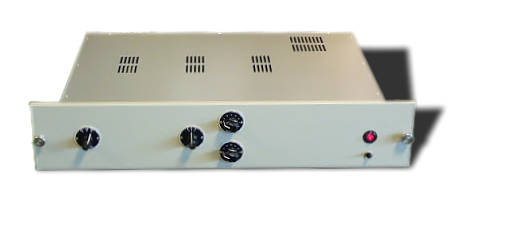
 Neumann's disc cutting system with lathe and electronics rack - circa 1968
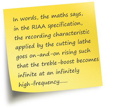
H(jω) = [(1 + jωT1) (1 + jωT3)] / (1 + jωT2)
where T1 = 3180µS, T2 = 318µS , and T3 = 75µS
From which it's fairly easy to see that H(jω) ⇒ ∞ as ω ⇒ ∞.
This is clearly not possible. No equaliser can ever provide infinite gain. And it wouldn't be desirable anyway because an equaliser with such a transfer characteristic would amplify any spurious supersonic signals and noise thereby putting the recording cutter-head amplifier, coils, chisel and lacquer under unnecessary stress.
This may seem something of an oversight. However, when the RIAA equalization standard was written, it was just assumed that the lathe manufacturer would include some kind of bandwidth limiting filter to define the upper skirt of the passband, which is exactly what they did.
It was suggested by Wright in The Tube Preamp Cookbook ¹ that Neumann cutting lathes incorporated this bandwidth defining filter by means of an extra, high-frequency pole at 3.18µS (50 kHz) in the cutting equaliser. The existence of this extra pole has become something of an urban myth.
Dubbing this extra time-constant, the Neumann Pole, Wright argued that, because the filter was single-pole and with a relatively "soft" roll-off, its effect was significant at audible frequencies. (It would cause about 1dB loss at 20kHz). Moreover, because Neumann lathes are by far and away the most common³, Wright argued that it would be prudent to add a complementary zero in the playback electronics; thereby to restore the overall record-replay transfer function to unity.
The theory of this is fine...... However, as you'll see, no such single-pole filter exists in Neumann cutting amplifiers (or probably those of any other lathe manufacturer).
The illustration below is a simplified schematic of the SE66 recording equaliser; part of the VG 66 disc recording system electronics rack.
In the SE66, the inverse RIAA characteristic is accomplished by the interaction of capacitors C1 and C2 with the other circuit impedances and op-amp gain. Essentially, as the reactance of C1 falls, the impedance of the input leg of the virtual-earth amplifier falls and the closed-loop gain rises from the 20Hz to about 500Hz (the start of the mid-frequency flat-section). After this point, the gain is held steady by the 18k resistor. For frequencies above this, the reactance of C2 falls so that C2 shunts more of the feedback voltage to ground and less to the virtual-earth summing point at the negative input of the op-amp. This causes the closed-loop gain to rise from about 2kHz until the circuit "runs out of HF gain" at some unspecified frequency.
Above the passband, the Sallen & Key, active filter formed around the BC107B emitter-follower rolls the high-frequency signal; its breakpoint being 33kHz. The loss due to this active filter is less than -0.5dB at 20kHz.
In other words: there is no 3.18µS (50 kHz) Neumann Pole in sight!
Interestingly, this circuit is heavily dependent on the choice and performance of the operational amplifier at its heart. Essentially, as stated, the T configuration in the feedback limb of the amplifier causes the amplifier to have a rising HF gain until it operates - to all intents and purposes - open-loop. The last pole (the Neumann Pole if you must) is thereby defined, not as a tidy time-constant at all, but by the dominant pole of the operational amplifier frequency-compensation.
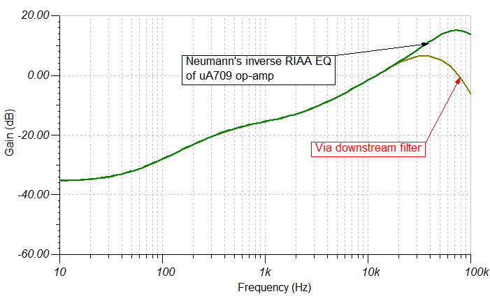
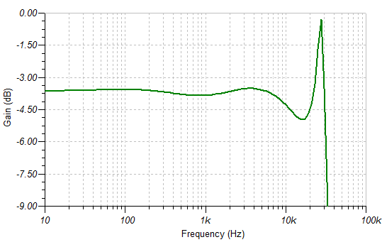
The choice of operational amplifier in the SE66 was Bob Widlar's paradigm-changing μA709. This was a fine component for its time but with a sluggish slew-rate by today's standards. Thanks to Neumann's engineers' solid understanding of the op-amp and their choice of external frequency-compensation components, the circuit response is very good. It rises to a peak about 70kHz before falling away due to the op-amp compensation. The combined effect the op-amp and of the following active-filter is illustrated in the figure below. Note how the active low-pass filter has no effect on response until above 20kHz.6
This reversal of the equaliser circuit topology in the later Neumann design was an odd decision because headroom is compromised in such an arrangement compared with the earlier SE66 equaliser as a result of the pre-emphasis stage carrying the full signal, rather than one in which the bass frequencies have already been removed. Nonetheless, the SAB-74B is said to be the most widely used equaliser in the cutting of contemporary records³, so its performance is of great interest. Does it implement the Neumann pole?
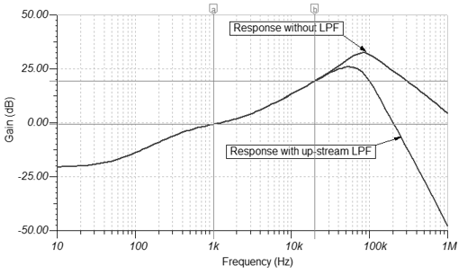
The answer is a definitive, no. Despite its apparent differences, the SAB-74B equaliser relies, once again, on the op-amp to provide rising HF gain way beyond 20kHz. The SAB-74B benefits from a more modern and better amplifier: the LF356 FET op-amp.
In fact, the characteristics of the LF356 op-amp would cause the gain of the SAB 74B to peak well outside of the audio band (100kHz) were it not for the presence of the up-stream supersonic filter which limits the peak to 50kHz. But, being an active filter with a reasonable Q, there is no appreciable effect upon the amplitude response at 20kHz as the figure below illustrates.
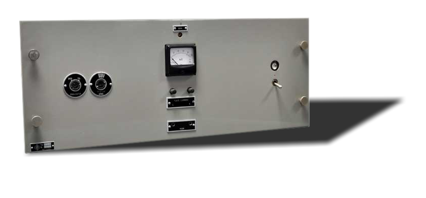
Neumann launched their first, stereo cutter-heads in the late 1950s. These were designed to be mounted on the Neumann AM-32b lathe and driven by a pair of Neumann LV60 tube (valve) power amplifiers (left). This was the Neumann solution for stereo recording up until the introduction of the VMS 66 in 1966.
Unlike later lathe electronics, the record equalisation was accomplished in the power-amplifier in this design. The schematic is given here. ⌘-click (right-click) for a larger version.
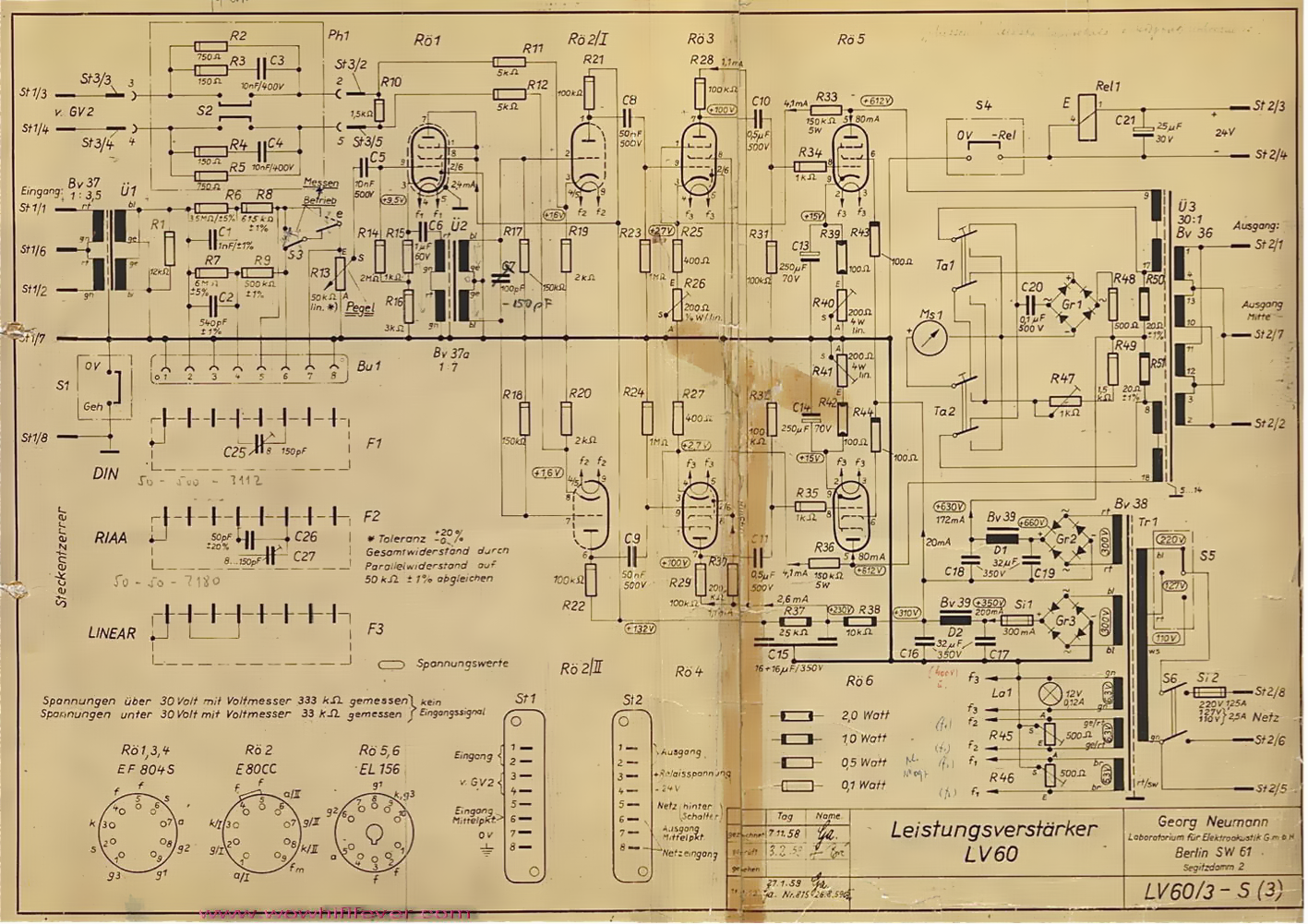
The LV60 is a push-pull, class AB amplifier which will deliver 60 watts into the recording-cutter coil. The equalisation is all performed in the passive RC network preceding R�1 (V1), the EF804 pentode � here run as a triode cathode-follower.
RIAA equalisation is determined by R7, R9, C2 and by C26 and C27 in the plug-in equalisers. (The plug-ins were made available so that recording equalisation could be switched between RIAA and DIN.)
 These components form a Lipshitz type-A equaliser configuration4. According to Lipshitz, the ratio between the two resistors, in a type-A configuration, should be 11.778 and the actual value of 12.0 is very close to this. The ratio between the two capacitors should be 3.6; thus, C26+C27 should be adjusted to 540pF / 3.6 = 150pF, which is in line with the given component values.
So far so good.
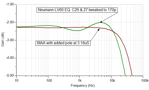
However, as Pspatial Audio's friend and acharya Gert Willmann pointed out to us, the equaliser is terminated in a relatively high resistance — the 50kΩ of R13, the Pegel or level control. This termination limits the amount of boost at high-frequencies relative to DC to (6MΩ + 500kΩ + 50kΩ) ⁄ 50kΩ = ×131 = 42dB which is just enough to cover the audio range to 20kHz but no more.
The result is that the boost is "running out of steam" at 20kHz and this does in fact introduce something like a Neumann-pole but, instead of being at 3.18µS (50 kHz), it is around 5.7µS (28 kHz). We've plotted the equaliser response (C27+C26 = 170p) against the "classic Neumann pole" response (see graph).
However, we urge caution deriving too much from this analysis of this sixty year-old equalisation circuit in isolation. The equaliser circuit is circumscribed by two transformers — one on the input and the other on the output. Audio transformers cannot be relied upon to provide an entirely flat frequency-response. So, there would have been more to the eventual response than just the equalisation circuit: the overall transfer function being due to a combination of the equalisation circuit and the wound components.
Making a few quesses as to the likely transformer parameters, we have simulated the frequency-response. It appears that the input transformer and its termination (Ü1, R1) provide a slightly falling response which is corrected in the capacitive "tweak" across the phase-splitter transformer (Ü2, C7). By this clever means, the response is maintained in the pass-band and a very sharp low-pass filter is formed to keep any anomalous, high-frequency energy away from the cutter.†
The output transformer may well have had an impact too, but note that the driver pentode and the output valves are in a negative-feedback loop (via R33/R36 to the cathodes of Rö3/Rö4).
In practice, the capacitor C7 was adjusted to give the correct response level at 15kHz relative to 1kHz - this being determined with test cuts and measurement using Buchmann Meyer patterns in the cut groove. The overall transfer characteristic would therefore have been adjusted to include the H(ω) of the output-transformer and cutter-head as well.5
† Gert Willmann noticed that this adjustable capacitor was modified from a fixed 100pF sometime between November 1958 and August 1959. This emphasises the critical nature of the undamped filter formed by C7 and the leakage inductance of Ü2 in obtaining an overall flat frequency-response.
The Neumann inverse-RIAA filters are all interesting circuits. The later operational-amplifier based equalisers turn out to be rather dependent on op-amp type and performance. But, it can be stated categorically that neither of the Neumann VMS series electronics deliberately introduced an extra, single-pole into the overall transfer function at 3.18µS (50 kHz); as Wright claims. These equalisers, despite the inclusion of supersonic, low-pass filters, adhere to the 6dB/octave rising response demanded by the RIAA standard at, and beyond, 20kHz. (For a discussion of phase-response, see the Appendix.)
The oldest equaliser - based on the tube LV60 power amplifier - has a limitation which appears to introduce something of an "extra pole" as the equalisation "runs out of gain" at high-frequency. But the effect of this is at a completely different frequency to that suggested by Wright (1995) and the the overall transfer-function of this equaliser must take these into account.
 We also know that the stereo monitoring equaliser designed to accompany the early Neumann lathes (the WV1 and WV2 - now regarded as super high-end phono preamplifiers) implement a relatively standard, Lipshitz type-B, RIAA feedback equaliser4 around a EF304 pentode tube for playback. So, no conjugate "Neumann Zero" exists to compensate for a "Neumann Pole"!
For these reasons, Stereo Lab software RIAA equalisation does not include the infamous Neumann pole in the transfer-function of the equaliser. Circuitry was never deliberately included to implement this in Neumann lathe electronics.
The Pspatial Audio Groove Sleuth Preamplifier similarly does not implement a zero at 3.18µS when the RIAA option is included.
Other names given for this pole in the replay transfer-function are 4th Pole or (incomprehensibly in the circumstances), Enhanced RIAA or eRIAA.
1. Wright A. (1995), The Tube Preamp Cookbook , Vacuum State Electronics.
2. Blauert, J. and Laws, P. (1978) Group Delay Distortions in Electroacoustical Systems Journal of the Acoustical Society of America Volume 63, Number 5, pp. 1478-1483 (May)
3. Self, D. (2010) Small Signal Audio Design. Elsevier
4. Lipshitz, S.P (1979) On RIAA Equalization Networks. Journal of the Audio Engineering Society Vol. 27 No. 6 June
5. Gotham Audio (1959) Technical notes to the AM-32b lathe
6. Thanks to Gert Willmann for pointing out that our original simulation of the SE66 used a unity-gain compensated µA709 in error.
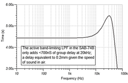
To some degree, this is correct: a zero above 20kHz on playback does introduce some phase-advance which compensates for some phase-lag introduced by the supersonic filter during recording. However, the phase-distortion of any active filter is best expressed in terms of group delay (the relative delay a filter imposes on various frequencies, or more technically ∂φ/∂f.) The group delay for band-limiting filter in the SAB-74B is illustrated below. It shows that the delay variation is <700nS; equivalent to the delay imposed by 0.2mm as sound travels in air and a result some 3000 times less than the threshold of audibility for group-delay at high-frequencies established as by Blauert and Laws.2
Home page
For all support issues, go here.
For Pspatial Audio sales, email: sales@pspatialaudio.com