In this application, we want the highest elastic modulus we can get for the cantilever, and we want the lowest density too (to ensure the lowest mass). But, in the table we have density and modulus of elasticity jumbled-up. We want a single measure for the best material for highest stiffness for a given weight.
The answer is to divide the figure for elastic modulus by the figure for the relative density, that's to say, E/ρ. We say that the cantilever material should have a high modulus of elasticity ratio. The materials are ranked (best to worst) in this way in Table. 2.
| Material |
Modulus of Elasticity Ratio (E/ρ) |
| C(s, diamond) Diamond |
28551 (kg/mm²) |
| B Boron |
19565 (kg/mm²) |
| Be Beryllium |
14674 (kg/mm²) |
| Al2O3 Sapphire or Ruby |
8000 (kg/mm²) |
| Al Aluminium |
2750 (kg/mm²) |
| Ti Titanium |
2422 (kg/mm²) |
The data, organised in this way, reveal that diamond is the best material for a stiff cantilever. But diamond (apart from the obvious expense), is notoriously hard to work and is rarely used in this application. Only the very top of the top-end products have attempted to use diamond as a cantilever. An example is the Koetsu Bloodstone Platinum cartridge, at the price of a new, small car.
Boron (atomic number 5, see appendix) is a metallioid — a chemical element with properties intermediate between those of typical metals and nonmetals. It has the highest modulus of elasticity ratio of any of the known elements except carbon in the form of diamond. Like diamond, boron forms covalent bonds which make it different from the metals aluminium, titanium, and beryllium, all of which form metallic bonds. The main uses of boron in industry are in the production of high-strength glass and ceramics (e.g. Pyrex) and as a component of metal alloys (boron steels). The isotope boron-10 is also used to make the control rods in atomic power stations.
It is difficult to produce a dense body of boron by casting or rolling methods so, the production of a boron cantilever involves "growing" the part by chemical vapor deposition (CVD). This is an involved and expensive process. Boron is an excellent choice for a rigid cantilever material and many high-end cartridges employ boron cantilevers, although, price and scarcity of the element are making it a more infrequent choice.
 Beryllium, lightest member of the alkaline-earth metals (atomic number 4, see appendix) would seem to be the next best choice for the cantilever material. Shure made high-end phono cartridge cantilevers from beryllium for a time and some manufacturers use beryllium as a component of an alloy. But this metal has serious problems in manufacture due to its toxidity. Breathing in beryllium in the workplace may cause berylliosis — a dangerous and persistent (and sometimes fatal) lung disorder which can also damage other organs, such as the heart. Beryllium is therefore nowadays rarely used for this application.
Emerald is a naturally occurring compound of beryllium.
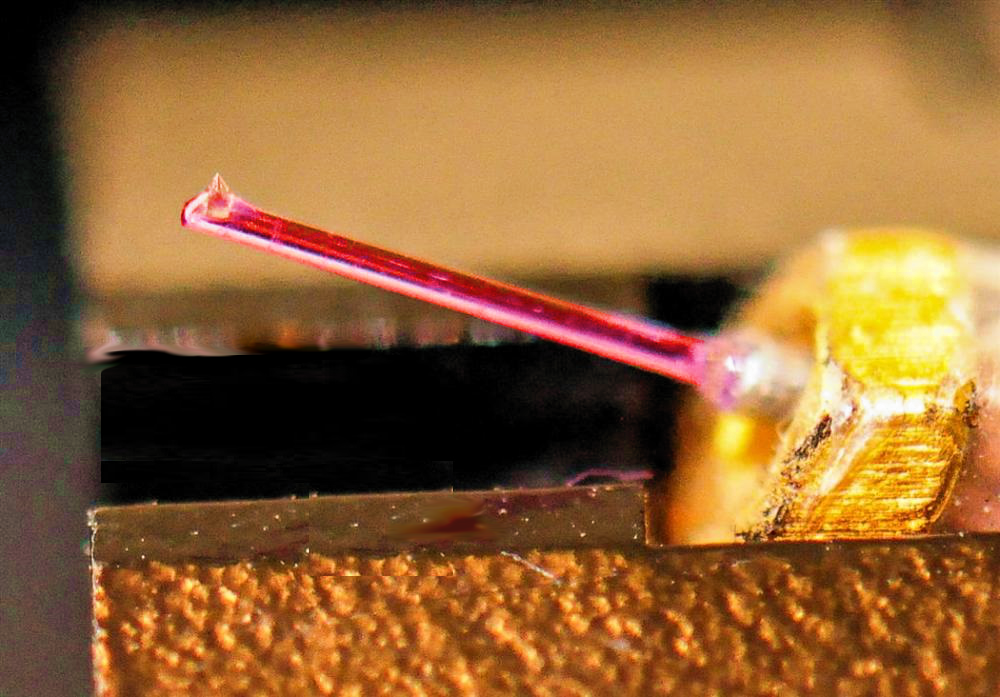
The mineral corundum (Al2O3) in the form of ruby or sapphire are both suitable for rigid cantilever construction (especially as both are made industrially) and are the choice of material in a range of high-end phono cartridges. The photograph (right) illustrates a cantilever formed from a solid rod of industrial ruby. From a conspicuous-consumption viewpoint, nothing comes close on to ruby on aesthetic grounds. Even diamond doesn't look as good. Boron — for all its material credentials — is, by contrast, positively drab.
The transition metal titanium (Ti), despite its low density, and high strength and its extensive use in aerospace and medicine, actually scores worse than aluminium for this application. Its most important property of corrosion resistance is hardly an issue in such a coddled application.
Shape and form
Cantilever performance is not simply dependent on the choice of materials: form matters too.
The tapered cantilever shape offers a refinement over a pure cylindrical form. Effective mass (seen from the stylus' point of view) increases the further mass is from the cantilever fixing (bearing). So, if the mass of the cantilever can be minimised towards the stylus, performance will be optimised. And a hollow pipe rather than a solid structure lowers effective mass too compared with a solid rod5.
It is in these ways that metallic aluminium (and lightweight aluminium alloys such as Duralumin) despite their somewhat "dowdy" image next to the exotic materials of diamond, boron, rubies and sapphires may score as a designer's choice of cantilever material8. Aluminium remains the material used for the great majority of phono cartridge cantilevers. Whilst not possessing the stiffness of the other materials, it is light, plentiful, cheap and easy to work and shape. Along with another surprise.....
Compliant cantilever
It turns out that an infinitely stiff cantilever may not be what's required anyway! It is possible to modify the simple electrical circuit analogy above to include the effect of the cantilever¹. First, let's reconsider the simplified model which eliminated the cantilever effects.
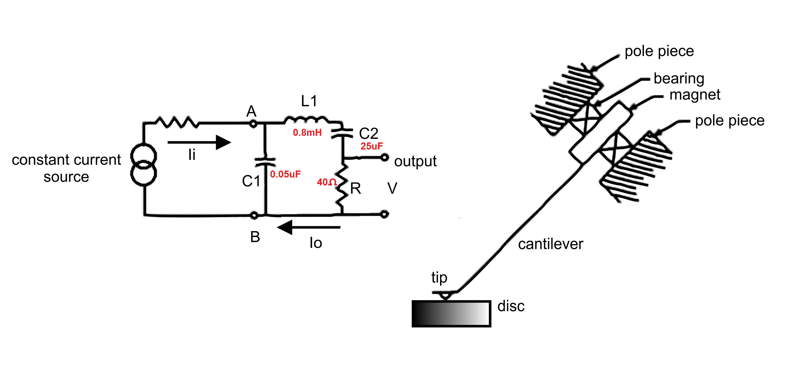 The various mechanical elements are represented by the electrical components as follows:
C1, represents - Record tip compliance µF = µ(cm/dyne)
C2 represents - Bearing compliance µF = µ(cm/dyne)
L1 represents - Inertia of armature (tip, cantilever and magnet) mH = mg
R represents - Viscous damping of bearing ohms = dyne-sec/cm
Ii represents - Recorded velocity Amperes = cm/s
Io represents - Output velocity of stylus Amperes = cm/s
Vab represents - Tracking force volts = grams
Now, let's split L1 (which represents inertia of armature: tip, cantilever and magnet) into two parts: L2 and L3; the former representing the tip end of the stylus assembly, and the latter, the magnet end of the stylus assembly. And let's add a new compliance (C3) to represent the compliance of the cantilever (as illustrated below).
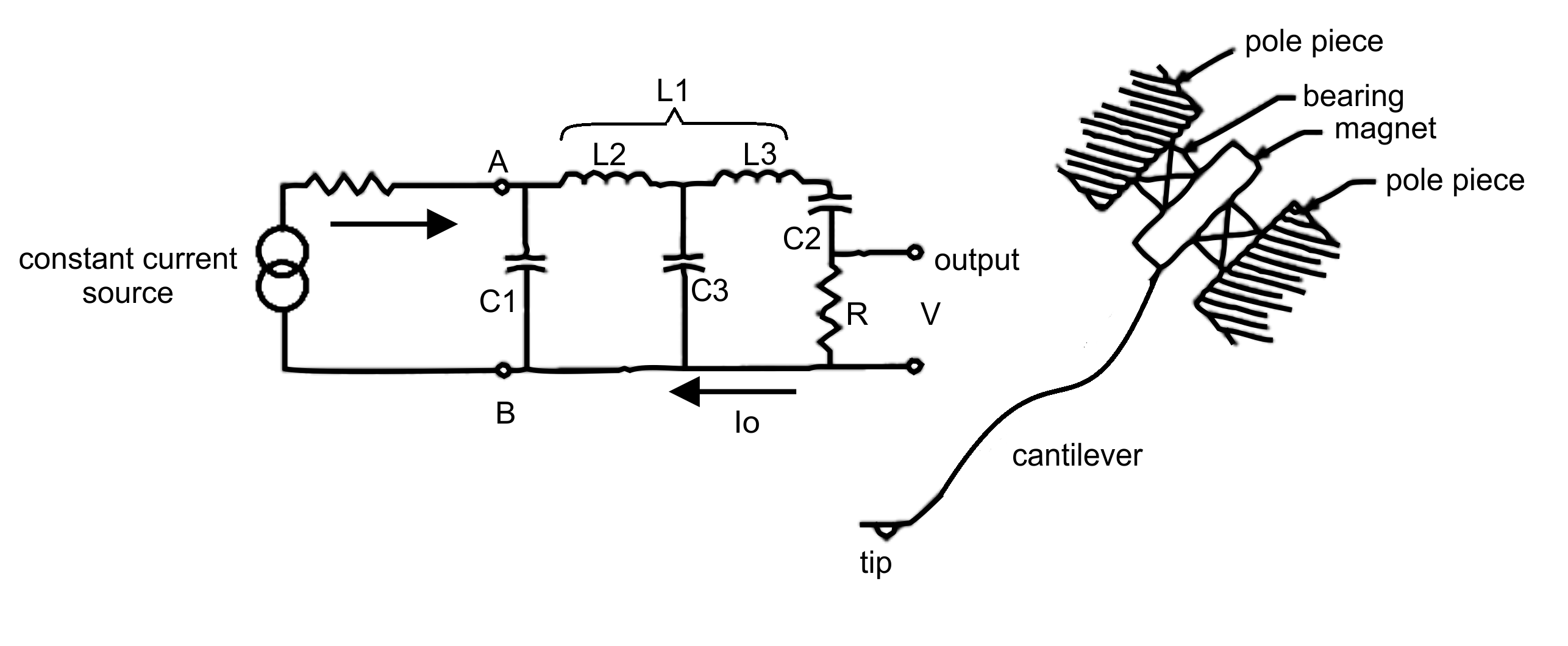
We perform the same analysis as we did before for the voltage Vab - which represent tracking force (volts = grams). But, this time, we include C3. We notice significant changes to the results obtained as we alter the value of this capacitor (representing a compliance).
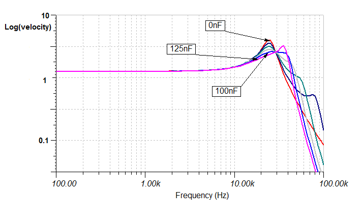
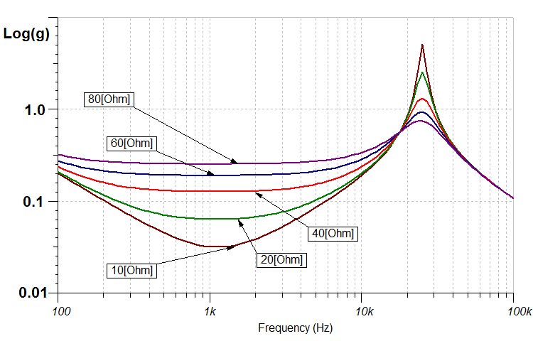
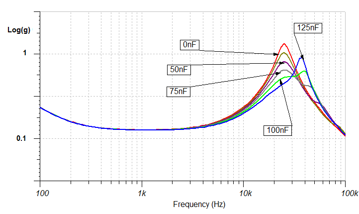 The curves are as illustrated (right). Compare this with the earlier graph. The red curve in this illustration, is the same as the red curve in the earlier graph to make comparison easier. That's to say a dampling value of 40Ω and C3 = 0.
Note the effect as the value of C3 is increased.
Above a certain point, C3 > 0.1µF (where µF = µ(cm/dyne)) the performance arguably deteriorates. But there is very clearly a broad range of values, where the tracking force requred to keep the stylus in the groove is reduced and the tracking is improved over the last octave of the recorded range with little or no effect upon the midrange performance.
This improvement is due to the non-zero compliance of the cantilever.
And, it's not simply the tracking which is improved. If we solve for Io, the output velocity of the stylus (in Amperes = cm/s), it demonstrates that the frequency-response is flattened too 7.
A mechanical explanation
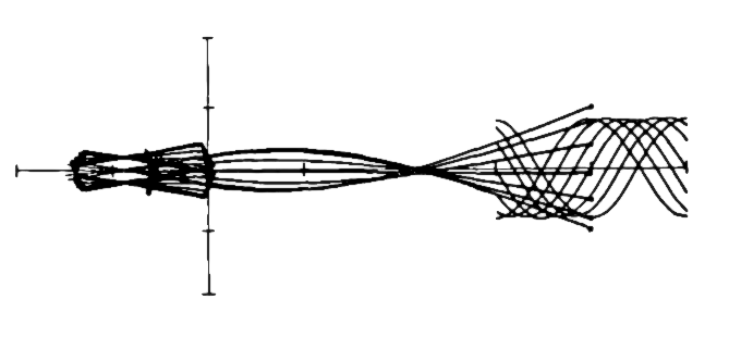
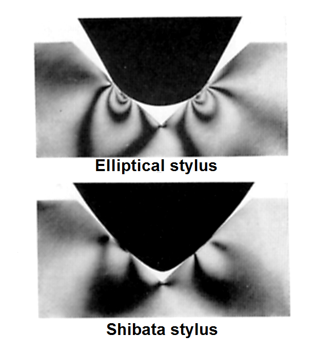
We can see a mechanical explanation for this counterintuitive result illustrated (left). The diagram shows the performance of the stylus, cantilever and magnet as overlaid images at successive instants of time, so that we see the positions of the components as if in consecutive frames of a movie film6.
The image illustrates that the bending of the cantilever partially decouples the movement of the stylus from the movement of the magnet. Whilst we might assume that we normally don't want this (on the basis of arm-waving, maximum information retrieval, maximum transmission of microvibrations type arguments), the model clearly demonstrates that, if the resonance of the cantilever is arranged to be broadly the same as the resonance of the tip end of the shank and the record material, the destructive effect of this latter resonance may be ameliorated by the former.
Which goes to prove that superficial arguments that a boron cantilever is automatically better than an aluminium cantilever seriously oversimplify the situation. The cantilever mass distribution (which may be modelled by altering the ratio of L2 and L3) and its compliance play an indispensable part in the overall performance of the cartridge.
".....superficial arguments that a boron cantilever is better than an aluminium cantilever seriously oversimplify the situation......... replacing the original manufacturer's cantilever with a .. component of more exotic material ought to be approached with caution."
Cantilever fever
Shure's Roger Anderson and his team¹ demonstrated that cantilever design was an integral part of a high-performance phono-cartridge. (It should be noted that the Shure team took great pains that this circuit analogy echoed the performance of real-world physical components.)
An infinitely stiff cantilever may not always offer the best solution and should certainly only be employed when an advanced stylus profile (like Shibata) ensures that the tip-plastic resonance is pushed to as high a frequency as possible. A rigid cantilever will offer no relief from this inevitable resonance on the tracking ability of the stylus. And tracking is king: an unyielding cantilever could introduce high-frequency mistracking with its insidious ability to damage records without betraying the damage it is doing.
Mathematical analysis (via circuit analogy) warns us that "upgrading" an existing cartridge by replacing the original manufacturer's cantilever with a "better" higher-performance component of more exotic material ought to be approached with caution.
Any cartridge (irrespective of its use of extravagant materials) needs to be carefully evaluated with extensive tracking tests before it is used for precision needle-drop recordings of valuable records.
Appendix 1 - Cantilever materials in the periodic table of the elements
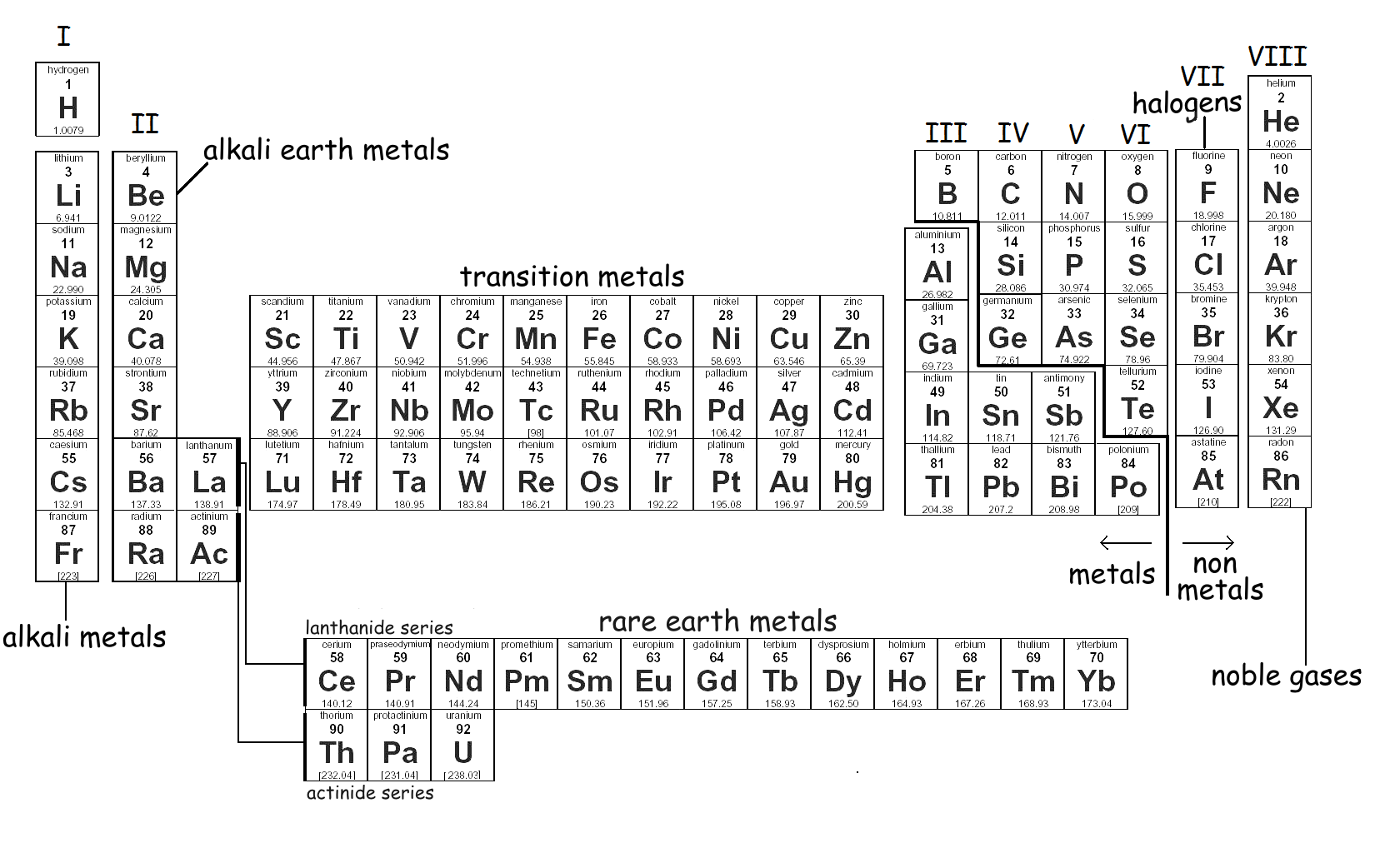 It's fascinating to note how the finest cantilever materials are adjacent in the periodic table. Beryllium (Be), Boron (B) and Carbon (C) are all adjacent in the same period. Beryllium (Be) is suitable but for its toxidity. Aluminium (Al) is in the same group as Boron and aluminium is suitable either as a refined metal or as aluminium oxide, in the crystalline form of ruby and sapphire (Al2O3). Magnesium (Mg) is sometimes found in an alloy with aluminium. Carbon, in the crystalline form of diamond, is best of all.
Appendix 2 - Mechanical equivalents
There exist fundamental similarities between electrical and mechanical networks. Not only is this simply interesting, it means that there are novel ways of approaching old problems. For example, the design of loudspeakers or phonograph pickups which, as engineering problems are normally conceived in the mind’s eye as a combination of springs and weights and dampers, may be modelled as the design of AC electrical networks and analysed using electrical filter theory.
There is a delightful irony here. First lessons in electricity always liken voltage to force or pressure, resistance to friction, and so on. But electrical engineers (despite starting later) have overtaken mechanical engineers to such an extent that it is often worthwhile translating mechanical quantities into electrical to get the benefit of the highly developed state of electrical circuit analysis and measurement techniques.
In the, so called, direct analogy:
- Force is represented by e.m.f. (voltage),
- Velocity is represented by current, and thus because d(displacement)/dt = velocity and dQ/dt = I,
- Displacement is represented by charge
- Mass by inductance,
- Compliance by capacitance (in mechanics, compliance is the inverse of stiffness)
- Resistance, reactance, impedance, etc., are common to both.
- Mechanical links, such as rods, are assumed massless, or their masses are represented separately in lumps and are largely treated in the same way as electrical connections.
This means that the electrical Ohm's Law has mechanical analogues. So that since we know,
V= I × R or V = I Z (if we allow for impedance) , we can deduce,
force = velocity × mechanical resistance (or impedance), and rearranging,
mechanical resistance = force ⁄ velocity
This process reveals more, and often less obvious, relationships, such that, electrical power = V × I, so mechanical power = force × velocity. And that compliance which we normally think of in mechanics as displacement ⁄ force is modelled in the electrical equivalent so that capacitance is equal to charge ⁄ voltage.
There even exists an analogy between the voltage that appears on a coil as a result of a change of current (like an HT coil in a car) and the relationship we all learnt at school between force, mass and acceleration because the voltage generated across an inductor is equal to the rate of change of current within its turns. Mathematically we can express this,
V = L dI/dt
By substituting the analogous quantities in the table above, we can see this is an analogue of,
Force = mass . d(velocity)/dt or,
F = mass . acceleration ....... or Newton's Second Law
Bringing in frequency
All the above has ignored frequency. Rather than thinking in terms of rates of change, and because we're thinking about sound reproduction, it helps enormously to know that just as the impedance of a capacitor is purely imaginary and is given by the well known equation,
Z = 1 ⁄ ( jωC)
the analogous mechanical impedance of a mechanical compliance (Cm) is given by,
Z = 1 ⁄ ( jωCm )
Similarly, the mechanical impedance of a mass (M) = jωM, just as the electrical impedance of an inductor (L) = jωL
References
1. Optimizing the Dynamic Characteristics of a Phonograph Pickup. Anderson, C.R., et al. Journal of the Audio Engineering Society April 1966, volume 14, number 2.
2. The Dynamic Vibration Absorber Principle Applied to
a High-Quality Phonograph Pickup. GROH, A.R.
Presented October 31, 1976, at the 55th Convention of the
Audio Engineering Society, New York. Journal of the Audio Engineering Society June 1977, volume 25, number 6
3.
Elastomers are not perfectly elastic and lose energy during the compression (or tension) and subsequent recovery. Unlike purely elastic substances, elastomers are viscoelastic which means that a substance has an elastic component and a viscous component. A viscoelastic element may be modelled as a perfect spring with a damper; or, in electrical terms, as a capacitance and a resistor.
4. Further Improvements in the Discrete Four-Channel Disc System CD-4. Owaki, I. et al. JAES June 1972, Vol. 20, No. 5.
5. A Hi-Fi Moving-Magnet Cartridge Using Recent Technology Obata, S. et. al. J.Audio Eng. Soc., Vol.32, No.3, 1984 March
6. Dynamic Modeling and Analysis of a Phonograph Stylus Happ, L.R. J. of the Audio Engineering Society, Volume 27, No. 1/2, 1979 January/February
7. Stylus velocity vs. variation in value of C3 (cantilever compliance).
8. What about high-performance plastics such as carbon fibre reinforced polymers ? Could these materials not be used for cantilevers? They have: Audio Technica make a low-end cartridge (the AT81CP) with a carbon reinforced ABS cantilever. With a modulus of elasticity ratio better than aluminium, it would seem that materials which play such a large rôle in contemporary engineering could be employed.
9. The Rational Design of Phonograph Pickups Hunt, F. V. JAES Vol. 10 No. 4, October 1962. This article sums up Hunt's work and that of his associates.
Links
 Pspatial Audio Home page
For all support issues, go here.
For Pspatial Audio sales, email: sales@pspatialaudio.com

© Pspatial Audio 2020. All rights reserved.  Apple Certified Developer. Stereo Lab, Aria 51, Aria 20, Head Space, Groove Sleuth, iLOOP and FRANCINSTIEN T-Sym are trademarks of Pspatial Audio. FRANCINSTIEN and Bride of FRANCINSTIEN (BoF) are trademarks of Phaedrus Audio. Macintosh and the Mac logo are trademarks of Apple Computer, Inc.
 If we searched for an individual who transformed the phonograph from a Victorian novelty to a modern marvel an excellent candidate would be Frederick V. Hunt who, as a young professor of physics at Harvard in 1936, was given the task of making phonograph recordings of the university's tri-centenary festival.
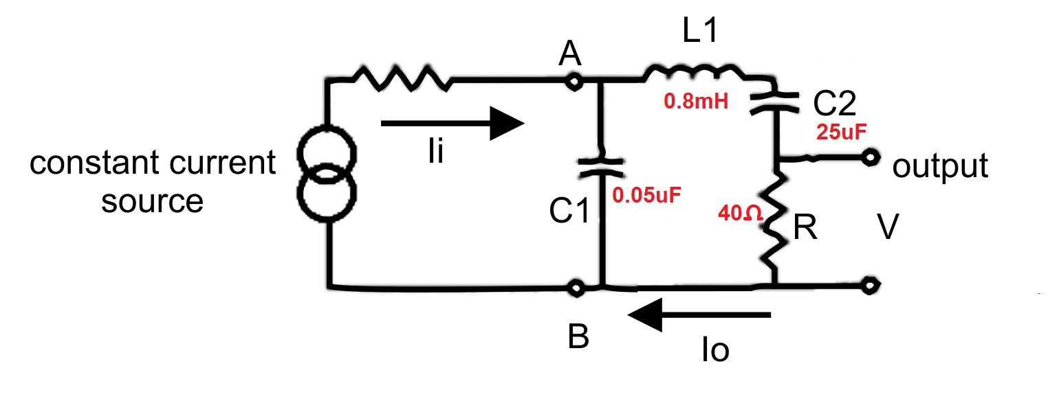 Concentrating of the circuit itself, we can see that it simpy two resonant circuits formed by L1 resonating in series with C2 and in parallel with C1; each being damped by R. Because of the huge difference in the values of C1 and C2, the two resonance frequencies will be widely separated and, to all intents and purposes they have little effect upon one another. Translating this back to a mechanical model, the mass of the armature (stylus, cantilever and magnet = L1) resonates with the main bearing compliance (C2) at an mid-band audio frequency, in this case at,
 L1 - The resonance due to the
  Table. 1 Cantilever material characteristics
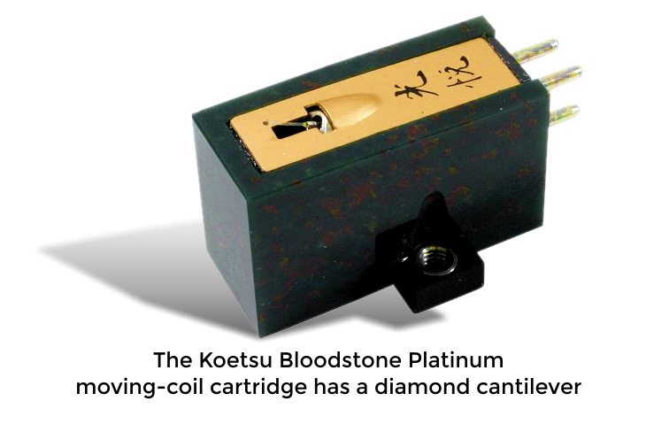 Table. 2 Cantilever material ranked by modulus of elasticity ratio