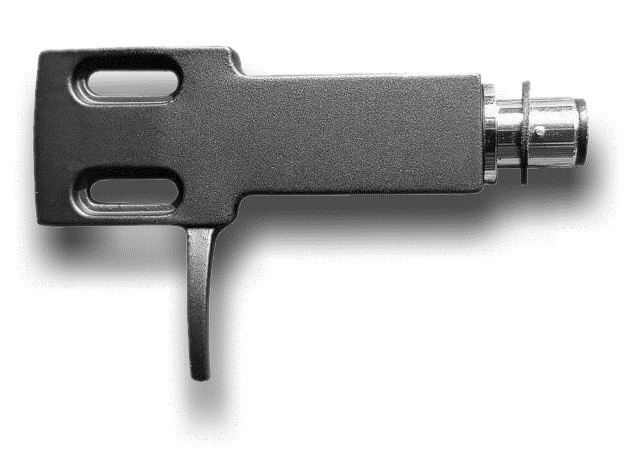
The headshell is a head piece platform, attached to the end of a turntable's tonearm, to which the phono cartridge is bolted.
Most phono cartridges offer a ½" (12.7mm) mounting holes (sometimes tapped) and the headshell is usually fabricated with ½" spaced slots to allow a cartridge to be mounted at the optimum effectve length of the tonearm.
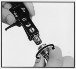
Most removable headshells (illustrated above) use an H-4 Bayonet Mount. A headshell of this type is widely known as an SME-type because the British tonearm manufacturer SME Limited pioneered this connector type on its widely used and admired products during the 1960s and 70s.
Better without?
The veteran, British hi-fi designer John Wright once said,
From the point of view of an ideal pickup cartridge the tonearm is merely a necessary evil.....The tonearm for the ideal cartridge can be envisaged as an inertia-less... device.¹
Considerations of low inertia always favour reducing the effective mass of the tonearm. This counsels the minimum of added complication and paraphernalia — especially at the stylus end of the tonearm.²
For this reason, many tonearm designers prefer to incorporate the cartridge platform into the tonearm itself and dispense with the need for a removable headshell. They see the addition of a headshell and its screw-locked connector as a compromise simply for convenience.
But it's compromise many users are quite happy to make. The separate headshell is a real boon to the DJ who may need to replace a cartridge under-pressure and in low-light. And it is a great asset to the record collector and archivist, because it means different cartridges with different styli may be fitted to different headshells and be swapped quickly and safely.
The physics
❝.... the movements of the cartridge will be transduced every bit as reliably as the movement of the stylus.❞
The electrical output from an electrodynamic cartridge is proportional to the difference in velocity between the stylus and the cartridge body. Therefore, when the stylus moves relative to a cartridge which is itself not still, the movements of the cartridge will be transduced every bit as reliably as the movement of the stylus.
A lightweight tonearm, made of lightweight materials, cannot support the pickup cartridge so rigidly that it may be considered a rest mass.4 The tonearm and headshell must be designed considering their vibrational properties because they too will contribute to the reproduced sound.
An intuitive way to test for this might be to flick the arm (or headshell) with a fingernail and listen to the "ping"! Lots of audiophiles do this and imagine that it is these high-frequency effects which must affect the sound. But this is a mistake.
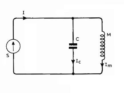
The equivalent circuit of a tonearm and cartridge (given left) explains why.
In the circuit, S is the source of the energy from the record groove and I is the current (modulation velocity). C is the compliance of the elastomer stylus bearing.
M is the mass of the arm referred to the stylus point and Im represents the arm velocity.
A little reflection will reveal that the quantity Ic is the all important velocity of the stylus tip relative to the arm. Because Ic = I - Im.
Seen as a simple electrical circuit it is obvious that for frequencies above the fundamental resonance of the arm and stylus compliance (where the impedance of C and M are equal and opposite), the stylus compliance will "decouple" the arm from groove modulation. This decoupling will become more effective at higher frequencies — as the impedance of C falls.
In consequence, the higher frequency arm resonances are very difficult to excite via groove modulation.6 The resonances which count are chiefly the low order longitudinal, torsional, and flexural resonances which exist at frequencies (up to a few hundred Hertz)4 where the impedance of C is not so negligibly small that Ic is unaffected by the impedance of M.
We will ignore the vibrations of the tonearm on this page and just concentrate on the effect of the flexion of the headshell.
Adding spring to the headshell
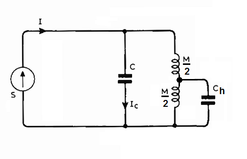
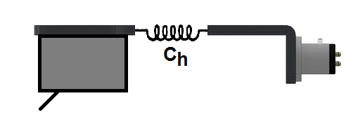
So far, we have treated the cartridge, headhell and arm as a single, unified mass (M). Now, let's split up that mass into two parts: 1) the cartridge and half the headshell; and 2) the second half of the headshell and the remainder of the tonearm.
We do this by inserting a compliance (a spring) into a perfect headshell as illustrated below (and right as the electrical equivalent, the capacitor Ch).
Inserting some real values³, we can say that the effective mass of the entire tonearm is about 20g and we can divide this into two halves 10g each. This is about right as the cartridge contributes nearly half the effective weight of the whole assembly because it's close to the stylus point. We'll set the cartridge bearing compliance to 12.5µ(cm/dyne) which is a typical figure.³
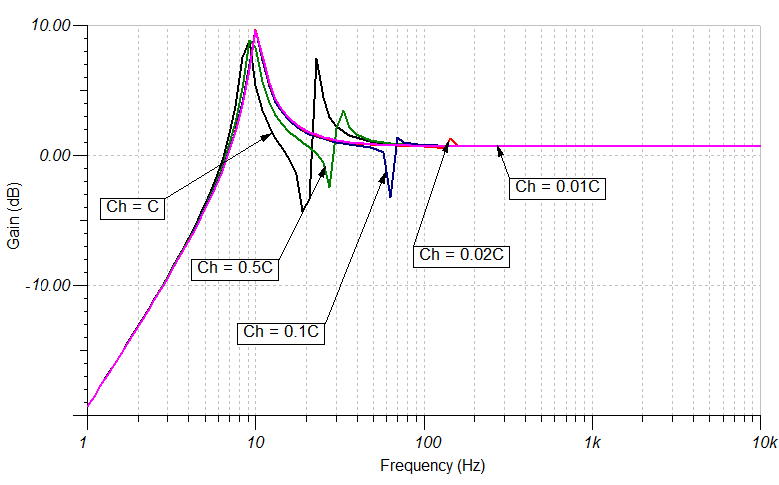
We can plot the transfer function of Ic for various values of Ch.
The main arm/cartridge resonance is evident from the peak at the extreme left (nicely placed at about 10Hz).
The disturbances at the frequencies above this resonance are due to the compliance Ch the values of which which are chosen to be stiffness multiples of the elastomer stylus bearing C. (Remember stiffness is the reciprocal of compliance.)
When the headshell is less than ten times stiffer than the elastomer bearing (Ch > 0.1C), it's clear that the cartridge will move relative to the tonearm by a significant amount (brown, green and blue traces).
But, once the stiffness of the headshell is 100 times greater than the bearing (Ch < 0.01C), the response is more or less indistinguishable from that when Ch = 0 with a single resonance peak and monotonic thereafter (purple trace).
So what material do we need to use so that the headshell is 100 times more stiff than our stylus bearing?
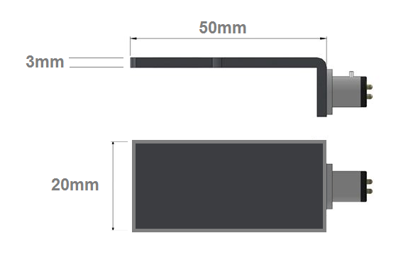
We can calculate the cross sectional area (A) of the material from the drawing of typical headshell dimensions (left) as 60mm². We know that,
Stiffness = Young's modulus × A⁄L,
where L is the length. (See Appendix 1 for derivation.)
Let's take a low-cost material like linear low-density polyethylene (think children's toys, plastic buckets etc.). This has a Young's modulus of around 0.1GPa (= 100,000,000 N/m²).
To recap, our stylus compliance is 12.5µ(cm/dyne) . Its stiffness is the reciprocal of this = 80,000 dyne/cm.
Thus a cheap, plastic headshell of the dimensions given is 1500 times more stiff than the elastomer stylus bearing. Easily stiff enough to prevent the cartridge from moving with respect to the tonearm by a margin of 15 times.
Material choices
A few cartridge types don't require headshells at all. P-Mount types are made to plug directly into special (often linear tracking) tonearms.
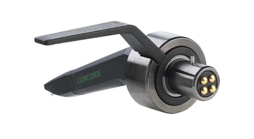
Another is the Concorde cartridge developed by the Danish company Ortofon. The Concorde fits directly into the H-4 Bayonet Mount and has a droop-nose with the body tapered to a small radius at the stylus apperture. This type is popular with DJs because the body and headshell don't obscure the stylus position and this allows for more accurate "cue-ing".
Aluminium
Recognisable in hundreds of household items, aluminium the most widely used non-ferrous metal. Aluminium is known for its good appearance, ease of fabrication and mechanical strength. By far the majority of headshells are of aluminium. At the low-end, they are usually die-cast or forged. High-end models are machined.
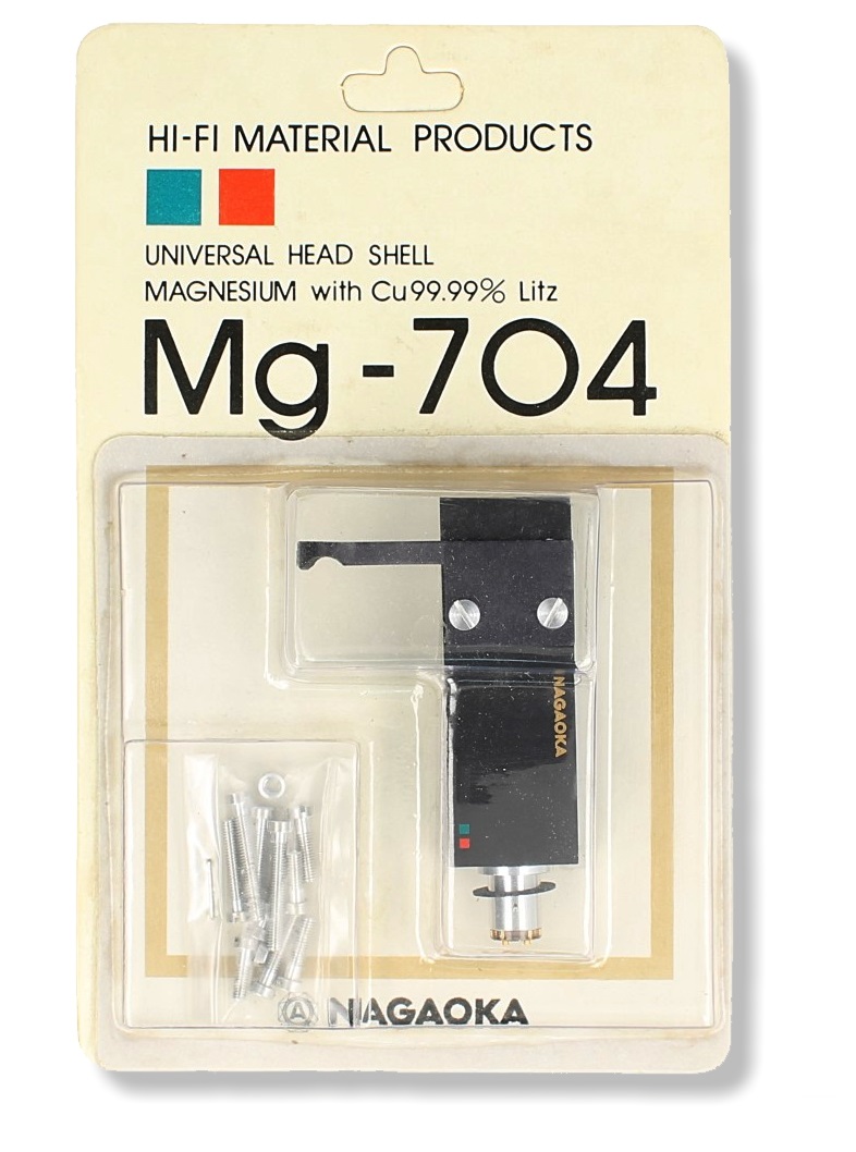
Magnesium
Magnesium is lighter than aluminium. (Magnesium has a density of 1700kg/m³ whereas aluminium has a density of 2700kg/m³.) That would seem to give magnesium an edge in this application. However, magnesium is softer with a Young's modulus of 45Gpa against aluminium's 69GPa.
Magnesium becomes much more ductile when alloyed with small amount of other metals, such as aluminium. Most "magnesium" headshells are, in fact, made from magnesium-aluminium alloy or are die-cast in a zinc alloy.
Cast components in magnesium may have thinner walls and tighter tolerances than an aluminium component. That is an advantage in a precision part like a headshell. But aluminium does not require as much finishing work as magnesium and forged aluminum is stronger than forged magnesium.
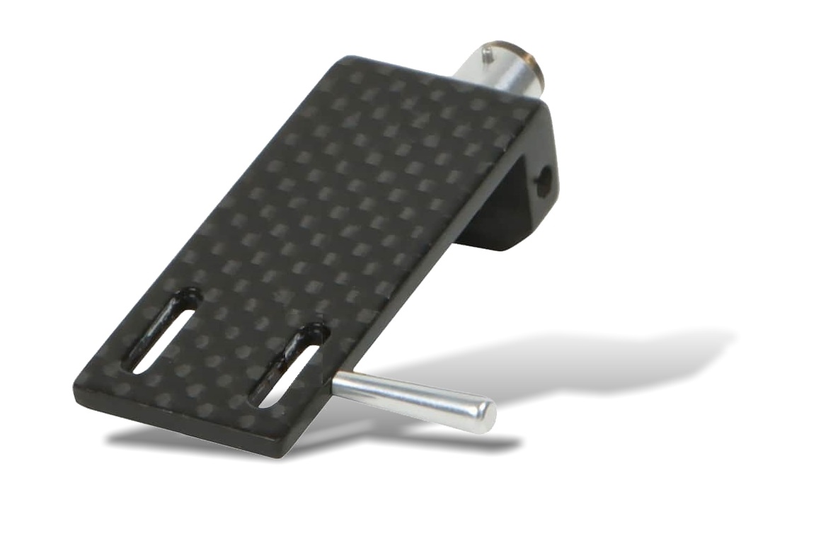
Carbon
Carbon fibre reinforced polymers (CFRP) are strong and light fibre-reinforced plastics; essentially a carbon-fibre weave in an epoxy polymer. Young's modulus for CFRP is 181GPa.
Carbon fiber composites have a density similar to magnesium (≈ 1700kg/m³). Put in a nutshell: CFRP combines the density of magnesium with the stiffness of steel!
Composites
The concept of a composite material is to combine materials of different properties so that the materials work together to give the composite of the individual material's properties.
Our bones are a composite made from a hard but brittle calcium phosphate and a soft and flexible material called collagen (which is a protein). Pictured is SteinMusic's 5-layer composite headshell, made with a middle layer of pear wood, framed by a carbon plate on both sides and rosewood outer wood.
Itself a composite, when wood is composited with other materials, the range of possible material performance becomes almost infinite. If composited with rigid materials, it is certainly plausible to obtain a composite performance combining the low density of wood and the rigidity of, for example, CFRP.
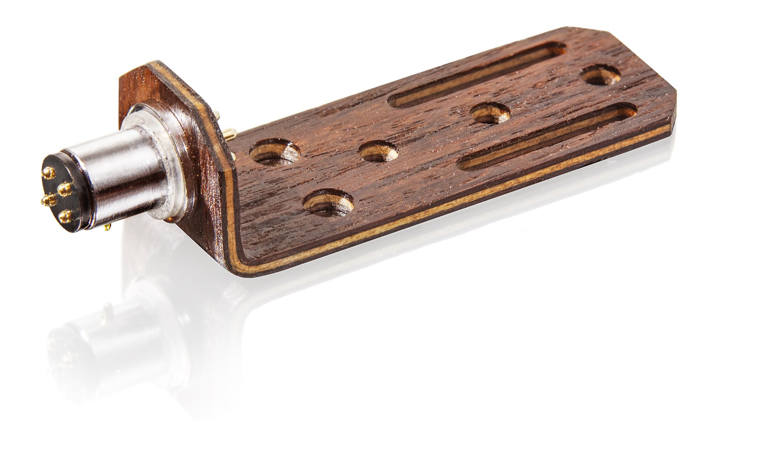
Wood
Wood is a natural composite material — long polymer fibres (cellulose) held together by the organic polymer lignin.
Woods of different trees and woody plants offer a staggering range of composite materials. Properties range from that of balsa wood with a density of 110kg/m³ and a Young's modulus of 1.5GPa, to eucalyptus with a density 1000kg/m³ and a Young's modulus of 15GPa. Figures typical for oak are a Young's modulus of 11GPa and a density of 750kg/m³.
Another analysis
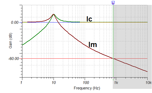
Thinking back to our equivalent circuit (left), we already noted that, higher frequency resonances of the tonearm and headshell will not be excited by groove modulation because, as the frequency of the modulation (I) increases, more and more of the energy is diverted into the Ic current mesh and away from Im mesh.6
At what point might we "draw a line" to define the energy is sufficiently small in the Im mesh that it is inconsequential?
There's no correct answer to this, but a ratio of 1:1000 (60dB) would seem to be a sensible watershed.
In the graph (right), Im and Ic are plotted against frequency. It illustrates that a 1000:1 division of current into the two current meshes occurs for frequencies above 800Hz.
Using this information, we have another way in which we may analyse the differences between headshells. We can calculate their resonance frequencies and see, to what degree they fall (or not) into the "danger zone" of the frequency region below 800Hz.
Headshell as a Kalimba !
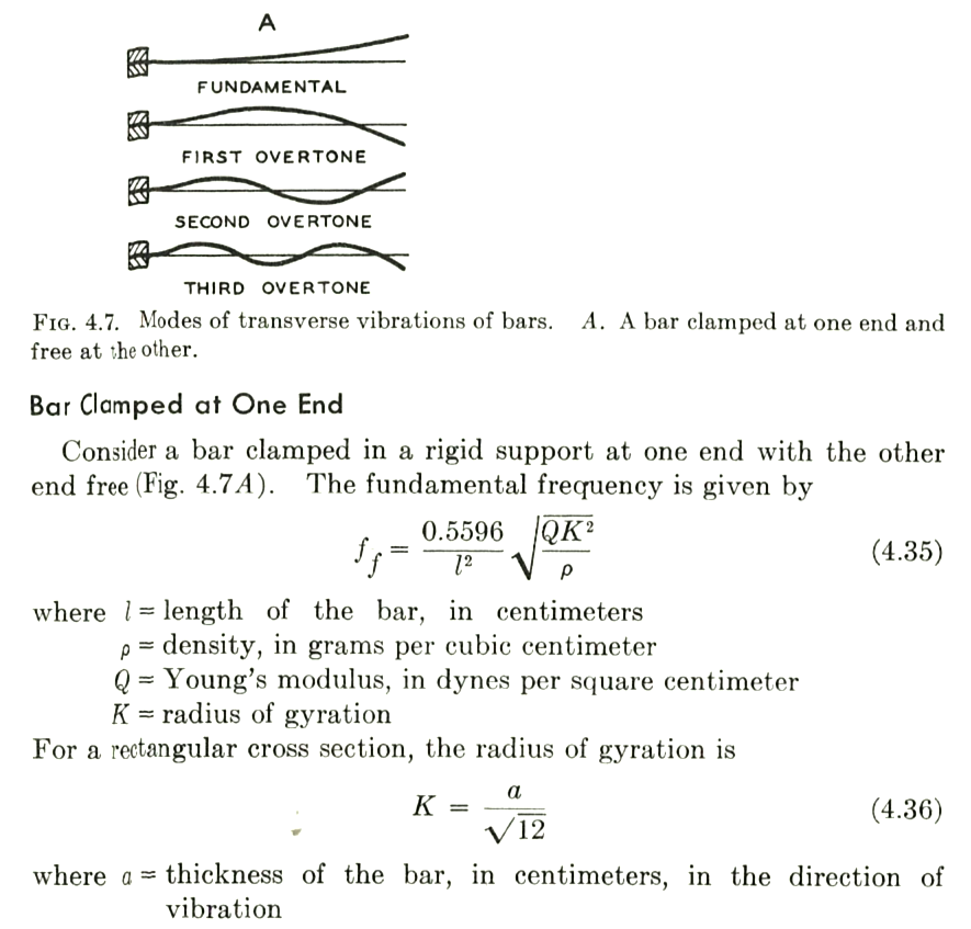
We can think of the of the headshell a bit like the resonanting bars of a mbira or kalimba, the African thumb-harp. Olson7 gave us all we need to calculate the resonant frequencies of a bar clamped at one end (given below). In the headshell, of course, it wouldn't be a firm thumb pluck, it's the energy directed into the tonearm from the record, which would excite the resonant bar.
Aluminium & Magnesium
Provided we have information regarding Young's modulus and density of the material and dimensions for the bar, we can use Olson's equation to determine the first three transversal resonances of the bar because they are related to the fundamental frequency (Ff) in a determined ratio: f1 = 1 × Ff; f2 = 6.267 × Ff; f3 = 17.55 × Ff.
If we do this for aluminium (we've assumed a thickness of 3mm and a length of 50mm), the first three resonanance frequencies are: 933Hz, 6.3kHz, and 16.3kHz. These are well into the zone where the stylus compliance will have "decoupled" any energy going to the cartridge body. Magnesium gives almost identical results.
Wood
A oak wood part produces the following sequence of resonance frequencies: 706Hz; 4.7kHz and 12.4kHz. Not that different from aluminium because the ratio between Young's modulus and density is not very different. But the first resonance of the 3mm thick, oak headshell is below our somewhat arbitrary 800Hz threshold. Increasing the material thickness to 4mm raises the first frequency to 940Hz — safely out of the way.
Carbon-fibre reinforced plastic (CFRP)
CFRP has a greater ratio of elastic modulus to density then either aluminium or magnesium, or wood and produces a series of resonances at higher frequencies: 1.9kHz; 12.8kHz and 33.4kHz, a splendid result!
Polyethylene
To go from the sublime to the ridiculous, if the headshell were formed of injection moulded LLDP (polyethyene), the frequencies would be: 60Hz; 400Hz and 1045Hz. We can see why headshells are rarely made like children's toys!
The headhell's effect on arm resonance
It is sometimes said that the choice of headshell ought to be influenced by the requirement to set the arm resonant frequency. The argument runs that if the resonance frequency is a little low and outside the magic 7Hz to 15Hz range, an aluminium headshell could be swapped for a one made of wood and vice versa.
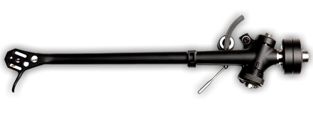
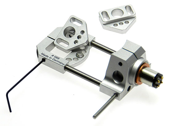
But there is much less scope here than one might wish for. A little research reveals that commercial removable headshell weights seem to range from about 8g for wood, to 10g for a lightweight aluminium "DJ" type, to 16g for metal construction (usually aluminium) "hi-fi" type. Even the remarkable, steampunk Arché design from Acoustical Systems (right) only weights 17.5g.
This gives us a range of about ±4 grams in a total effective mass of about 20g (remember M in the equivalent circuit), say 16g to 24g total which gives us a total range5 of about ± 10% in arm resonance frequency, or ± 1Hz. Not enough to worry about and certainly not enough to be a useful mechanism for adjusting the performance a of a poorly matched arm and cartridge.
Conclusion
It would have been great to back up the above theoretical analyses with some experimental evidence. But we could devise no practical experiments to reveal the differences between headshells of different design. Standard tests and test records betrayed nothing.
This, combined with the fact that two different mechanical analyses reveal that all the materials under serious consideration on this page are adequately stiff for the role of headshell, lead us to the happy conclusion that, unlike the market for turntable mats, the consumer is remarkably well served with competent headshell products at all price points. One might cavil at the price at the very high-end. But to criticise would be peevish and puritanical in a luxury goods market.
This leads us to our recommendation of wood as the best headshell material — based on weight. Provided the material has adequate stiffness, the lowest mass is preferable in this application. Even if the tonearm designer has sacrificed low inertia in search of better mechanical damping, it makes sense not to compound the decision and raise the effective mass of the tonearm assembly with a heavy headshell.²
Wood is adequately stiff and is the least dense material. It proved a bit marginal in the "kalimba" analysis. A wooden headshell needs to be thicker than an equivalent part in aluminium. But this is still consistent with the lowest weight because woods are greatly less dense than aluminium - or even magnesium or CFRP.
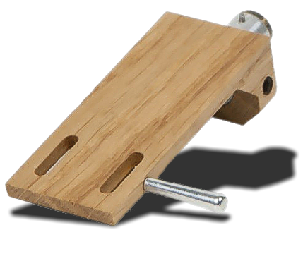
Oak is a good choice with a density a ¼ that of aluminium. Ortofon make a very attractive part in oak with the clever trick of having the cartridge fixing screws do double-duty as the handle fixing (left). It weighs 8.5g. Unfortunately it is costly.
Carbon fibre reinforced plastic has a very high elastic-modulus to density ratio and the "kalimba" analysis revealed that this pushed resonance frequencies well above the range of concern which is excellent. In composite with wood, exceptional performance is, no doubt, obtainable.
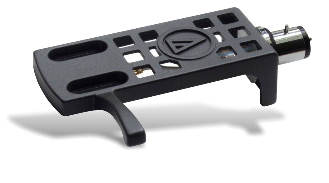
If you need a selection of cartridges to hand for different duties: stereo; mono; CD-4; shellac discs; 45s, and so on and this precludes the use of multiple expensive headhells, Audio Technica make a very good die-cast aluminium part (shown right) which only weighs 10g at a very reasonable cost.
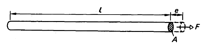
Let's think about a metal wire under tension so as to define the terms stress, strain and Young's modulus.
When a force F (in this case tension) is applied to the end of a wire of cross-sectional area A, as shown, the tensile stress = force per unit area = F/A. In SI units, A is expressed in metres² and F in Newtons. Newtons/metres² has its own SI unit such that 1N/m² = 1 Pascal.
If the extension of the wire is e, and its original length is l, the tensile strain = extension per unit length = e/l (in metres in the SI system).
Suppose 1 kg is attached to the end of a 1 metre length wire of diameter 1.0 mm, and the extension is 0À50 mm. Then,
Note that stress has units (N/m² or Pascals), but strain has no units because it is the ratio of two dimensions (lengths in this case).
The modulus of elasticity of the wire, called Young's modulus (E), is defined as the ratio,
E = stress ⁄ strain , and that,
E = (F/A) ⁄ (e/l) = (F . l) ⁄ (A . e) . Thus, F/e = (E . A) ⁄ l
Notes and References
1. An approach to pickup arm design. Wright, J.S. Wireless World April 1967
2. If that's not obvious, just think of the groove's role in dragging the tonearm across the disc surface and accelerating the effective mass of the tonearm in the intertracks and lead in/out grooves. The greater the mass, the greater the force required to accelerate the arm.
In considering the various components of the tonearm, we should bear in mind that the inertial mass of a pivoted straight bar is set by, θ = m Î d² where θ is the moment of inertia in gram metres² of a point mass m in grams that is located a distance d millimetres from the rotational centre of the system. Because d is squared, it should alert us to the important fact that distance (from the pivot) dominates over straightforward mass.
3. These physical values translate to 20H for the inductor and 12.5uF for the capacitor in the electrical equivalent circuit. Note that, the component C in this circuit is the same component as C2 which forms part of the equivalent circuit of the cartridge.
5. Remember that the equation F = [2.Π.√(M.C)] -1 reveals that resonant frequency only changes with the square-root of the mass (or the compliance).
6. You might be thinking, but what about the damping of elastomer bearing C ? Perhaps that can shunt energy into the arm irrespective of frequency? The answer is that indeed it does! We include damping of the stylus bearing in the equivalent circuit as a resistor in series with C. (Refer to the equivalent circuit of a cartridge where it is R in series with C2.) The effect of any damping of the stylus bearing is included in this analysis by including a low value resistor (100Ω) in the model which wasn't shown for clarity.
7. Music, Physics and Engineering. Olson, H.F. Dover Publications Inc. New York.

 The headshell is a head piece platform, attached to the end of a turntable's tonearm, to which the phono cartridge is bolted.
 Considerations of low inertia always favour reducing the effective mass of the tonearm. This counsels the minimum of added complication and paraphernalia — especially at the stylus end of the tonearm.²
 So far, we have treated the cartridge, headhell and arm as a single, unified mass (M). Now, let's split up that mass into two parts: 1) the cartridge and half the headshell; and 2) the second half of the headshell and the remainder of the tonearm.
 So what material do we need to use so that the headshell is 100 times more stiff than our stylus bearing?
 Another is the Concorde cartridge developed by the Danish company Ortofon. The Concorde fits directly into the H-4 Bayonet Mount and has a droop-nose with the body tapered to a small radius at the stylus apperture. This type is popular with DJs because the body and headshell don't obscure the stylus position and this allows for more accurate "cue-ing".
 Recognisable in hundreds of household items, aluminium the most widely used non-ferrous metal. Aluminium is known for its good appearance, ease of fabrication and mechanical strength. By far the majority of headshells are of aluminium. At the low-end, they are usually die-cast or forged. High-end models are machined.
 Carbon fibre reinforced polymers (CFRP) are strong and light fibre-reinforced plastics; essentially a carbon-fibre weave in an epoxy polymer. Young's modulus for CFRP is 181GPa.
 The concept of a composite material is to combine materials of different properties so that the materials work together to give the composite of the individual material's properties.
 Wood is a natural composite material — long polymer fibres (cellulose) held together by the organic polymer lignin.
 At what point might we "draw a line" to define the energy is sufficiently small in the Im mesh that it is inconsequential?
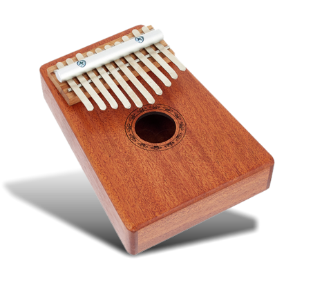 We can think of the of the headshell a bit like the resonanting bars of a mbira or kalimba, the African thumb-harp. Olson7 gave us all we need to calculate the resonant frequencies of a bar clamped at one end (given below). In the headshell, of course, it wouldn't be a firm thumb pluck, it's the energy directed into the tonearm from the record, which would excite the resonant bar.
 It is sometimes said that the choice of headshell ought to be influenced by the requirement to set the arm resonant frequency. The argument runs that if the resonance frequency is a little low and outside the
 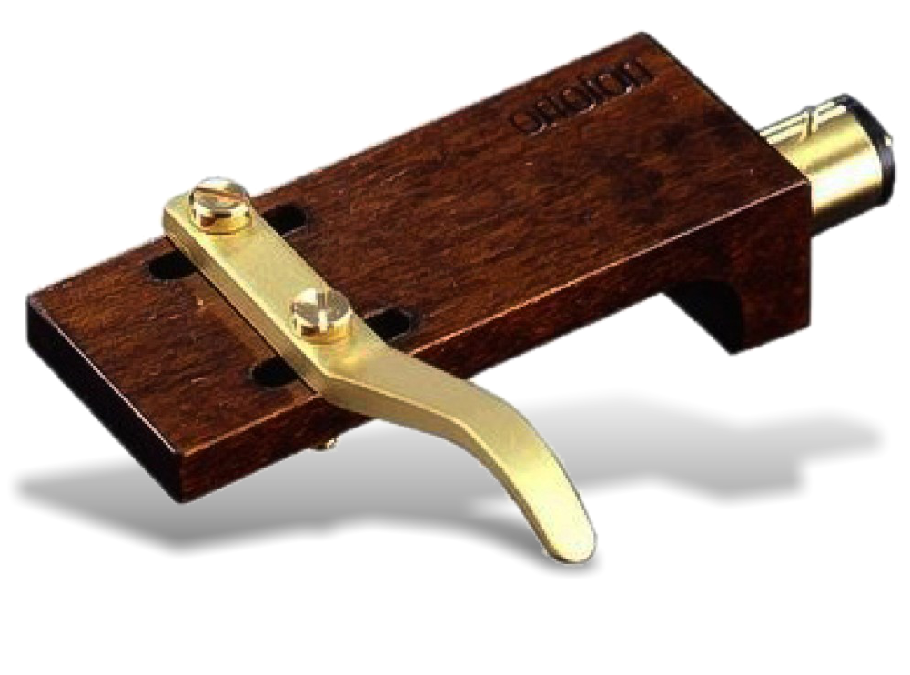 This leads us to our recommendation of wood as the best headshell material — based on weight. Provided the material has adequate stiffness, the lowest mass is preferable in this application. Even if the tonearm designer has sacrificed low inertia in search of better mechanical damping, it makes sense not to compound the decision and raise the effective mass of the tonearm assembly with a heavy headshell.²
 Oak is a good choice with a density a ¼ that of aluminium. Ortofon make a very attractive part in oak with the clever trick of having the cartridge fixing screws do double-duty as the handle fixing (left). It weighs 8.5g. Unfortunately it is costly.
 Let's think about a metal wire under tension so as to define the terms stress, strain and Young's modulus.